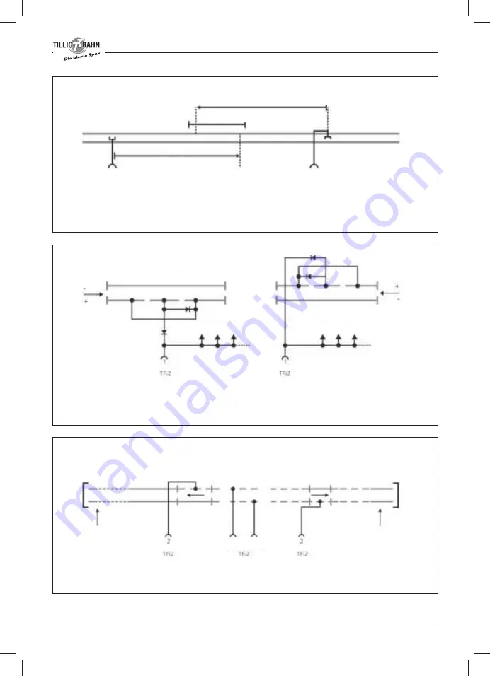
Terminal external control
The rail contacts of each direction must be installed at an appropriately long enough distance before
the “stopping point” of the train according to the selected delay. In the event of different vehicles a
different braking distance will be set in the event of the same time delay. This is brought about by the
different speeds of the traction vehicles at the same level of voltage.
The Y-points must be installed in such a way that the output towards the TFi2 is located to the right in
the drive direction (the potential of this rail is „+“). The stopping of the traction vehicle is only triggered
if the potential directed to the TFi2 is „+”.
A shuttle route can be set up by installing the y-points at the end of the line and their connection to
the second control terminal of the TFi2.
14
Representation of the position of Y-points to trigger the stopping mechanism:
Circuit for an intermediate station:
Circuit for the terminal station of the shuttle route (without representation of stops):
Braking distance
Stopping point
Braking distance
Y-point
Drive direction
Additional y-points
Additional y-points
Drive direction
Y-point
Y-point
End point
= turning point
End point
= turning point
Effective
Drive direction
Effective
Drive direction
Rail connection


