background image

24

Chapter 3

Benchtop (Local Mode) Tutorial

3.7

Jogging

In ‘Local’ mode, the motor actuators can be jogged using the front panel arrow keys,
or by using an optional jog handset connected to the MOTOR CONTROL port on the
rear panel of the unit (see Section 2.5. for details on the jog handset). There are two
jogging modes available, ‘Single Step’ and ‘Continuous’. In ‘Single Step’ mode, the
motor moves by the step size specified in the Step Distance parameter. If the jog key
is held down, single step jogging is repeated until the button is released - see Fig. 3.6.
In ‘Continuous’ mode, the motor actuator will accelerate and move at the jog velocity
while the button is held down.

1) Press the 

 key until the channel 1 led is lit.

2) Press the 

 key to enter the Setup menu. The display then shows the parameter

most recently selected. 
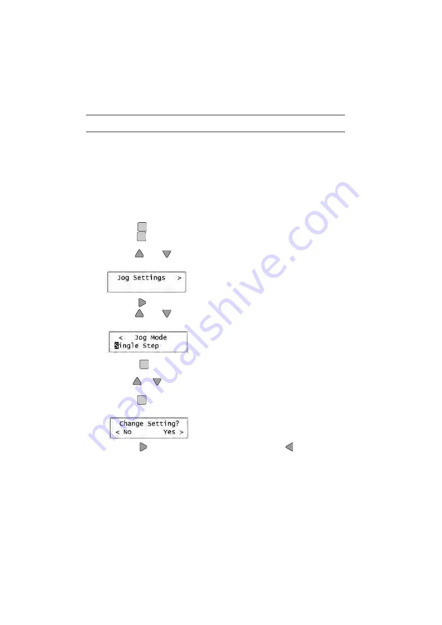
3) Use the 

 and 

 keys to scroll through the parameter list and select the

Jog Settings    > 

parameter.

4) Press the 

 key to enter Jog Settings menu.

5) Use the 

 and 

 keys to scroll through the parameter list and select the

<

Jog Mode 

parameter.

6) Press the 

 key to enter the Edit mode. The first letter of the current value

flashes.

7) Use the 

 or 

 keys to adjust the displayed value to Single Step (The default

factory setting). 

8) Press the 

 key to save the setting.  The unit asks whether you want to save the

change by displaying ‘

Change Setting?


< No    Yes >

’.

Press the 

 key to save the change (you would use the 

 key to leave the

value unchanged).

Chan

Menu

Save

Menu

Save

Menu

Save

Содержание BMS001

Страница 1: ...advanced positioning technology STEPPER MOTOR CONTROLLER Model Numbers BMS001 and BMS002...

Страница 2: ...tly develop optimal positioning solutions As a part of Thorlabs inc manufacturers of innovative photonics products we are committed to providing the service relationships and attention to detail that...

Страница 3: ...on 10 Menu Navigation 10 Motor Moves 11 Installing APT Software for PC Remote Operation 12 Introduction 12 Software Installation 12 Software Upgrades 13 APT PC Software Overview 13 Introduction 13 APT...

Страница 4: ...Settings Panel 49 Appendices A Rear Panel Connector Pinout Details 54 Rear Panel Motor Control Connector 54 Rear Panel Drive Channel Connectors 56 B Preventive Maintenance 57 Safety Testing 57 Fuses...

Страница 5: ...on the equipment Warning risk of danger Refer to the handbook for details on this hazard Warning risk of electric shock High voltages present Equipotentiality bonding terminal Functional EMC earth gr...

Страница 6: ...336 EEC EMC Directive and 73 23 EEC Low Voltage Directive as amended by 93 68 EEC Compliance was demonstrated by conformance to the following specifications which have been listed in the Official Jou...

Страница 7: ...oftware Remote mode is available In Remote mode the unit can be connected to a PC via the USB port A fully featured software suite is provided the APT system software and once installed on the PC comp...

Страница 8: ...non condensing at 31 C To ensure reliable operation the unit should not be exposed to corrosive agents or excessive moisture heat or dust If the unit has been stored at a low temperature or in an envi...

Страница 9: ...are a useful mechanism for implementing an external emergency stop feature Motor jogging lines can be used to jog the motor in both forward and reverse directions Jogging parameters e g jog distance c...

Страница 10: ...g sequence is initiated when the Move key is pressed Rel Move Mode A relative move is initiated when the Move key is pressed Abs Move Mode An absolute move is initiated when the Move key is pressed Mo...

Страница 11: ...eys or a remote PC To allow this kind of use Thorlabs can supply a jog handset which enables the motors to be jogged at some distance from the controller itself or a remote PC The handset is supplied...

Страница 12: ...key to enter the Edit mode For value parameters the least significant digit is highlighted To change this digit press the and keys To select other digits to edit use the and keys to navigate to the d...

Страница 13: ...1 Pos Ch2 000 000 000 000 Chan Calibration 001 000 Local Remote Local Panel Menu Save Menu Save Menu Save Local Panel Remote USB Oper Limits Max Vel Lim Max Accn Lim Max Position Min Position press to...

Страница 14: ...1 Power up your PC Caution Item 2 must be performed before item 3 2 Insert the Installation CD into your CD drive 3 Using the USB cable provided connect the APT unit to your PC 4 Switch On the power t...

Страница 15: ...custom software Both utilities are built on top of a sophisticated multi threaded ActiveX engine called the APT server which provides all of the necessary APT system software services such as generat...

Страница 16: ...ing configurations to be created and easily applied For many users the APTUser application provides all of the functionality necessary to operate the APT hardware without the need to develop any furth...

Страница 17: ...ng the APT software These settings have global effect such as switching between simulator and real operating mode associating mechanical stages to specific motor actuators and incorporation of calibra...

Страница 18: ...a wide range of software development environments for use by client application developers Development environments supported include Visual Basic Labview Visual C C Builder HPVEE Matlab VB NET C NET...

Страница 19: ...rs Note that the APTUser and APTConfig utilities take advantage of and are built on top of the powerful functionality provided by the APT ActiveX Server as shown in Fig 2 5 Fig 2 5 System Architecture...

Страница 20: ...l steps described in Chapter 3 for further verification of operation Note The APT Config utility can be used to set up simulated hardware configurations and place the APT Server into simulator mode In...

Страница 21: ...he LCD panel but internally microsteps are used to position the motor see Appendix D Section D 1 for an explanation of microsteps The calibration factor is used by the unit to convert between the real...

Страница 22: ...limit switches provide a fixed datum that can be found after the system has been powered up 1 Press the key until the channel 1 led is lit 2 Press the key repeatedly to select the Home mode for channe...

Страница 23: ...to enter the Edit mode The 6th digit i e least significant digit flashes 6 Use the key to select the 3rd digit then use the and keys to adjust the displayed value to 002 000 This relates to an absolu...

Страница 24: ...e Edit mode The 6th digit i e least significant digit flashes 6 Use the key to select the 3rd digit then use the and keys to adjust the displayed value to 002 000 This relates to a relative move of 2m...

Страница 25: ...arameter 6 Press the key to enter the Edit mode The 6th digit i e least significant digit flashes 7 Use the key to select the 4th digit then use the and keys to adjust the displayed value to 000 400 T...

Страница 26: ...ty while the button is held down 1 Press the key until the channel 1 led is lit 2 Press the key to enter the Setup menu The display then shows the parameter most recently selected 3 Use the and keys t...

Страница 27: ...the motor will accelerate at 0 2mm sec sec until the Jog Velocity is attained 10 Press the key until the channel 2 led is lit then repeat items 2 to 8 to set the following parameter values Jog Mode C...

Страница 28: ...gh the parameter list and select the Local Remote parameter 3 Press the key to enter the Edit mode The L of the Local Mode flashes 4 Use the or keys to adjust the displayed value to Remote USB 5 Press...

Страница 29: ...most recently selected 3 Use the and keys to scroll through the parameter list and select the Jog Settings parameter 4 Press the key to enter Jog Settings menu 5 Use the and keys to scroll through th...

Страница 30: ...umber of parameters must first be set These parameters relate to the physical characteristics of the stage being driven e g min and max positions leadscrew pitch homing direction etc To assist in sett...

Страница 31: ...ect the channel number to be configured 6 In the Stage field select the ZST6 actuator type from the list displayed for a 6mm travel ZST actuator 7 Click the Add Stage Association button 8 Shut down th...

Страница 32: ...multiple graphical instrument panels to be displayed so that multiple APT units can be controlled All basic operating parameters can be set through this program and all basic operations such as motor...

Страница 33: ...played in the Settings window See Section 4 9 and Section 6 3 for further details on the parameter values shown in the Settings display Fig 4 9 Motor Controller Software GUI Dual Channel Version The A...

Страница 34: ...system has been powered up Fig 4 10 Motor Controller Software GUI Dual Channel Version 1 Click the Home buttons for Channel 1 and Channel 2 Notice that the led in the button lights to indicate that ho...

Страница 35: ...n real world units e g millimetres relative to the Home position 1 Click the position display associated with channel 1 Fig 4 11 Absolute Position Popup Window 2 Enter 3 0 into the pop up window 3 Cli...

Страница 36: ...k the Channel switch to select channel 1 2 On the GUI panel click the Settings button bottom right hand corner of the display to display the Settings panel Fig 4 12 Settings Panel Channel 1 Move Jogs...

Страница 37: ...epeated until the button is released see Fig 3 6 In Continuous mode the motor actuator will accelerate and move at the jog velocity while the button is held down 1 Click the Channel switch to select c...

Страница 38: ...d to developing custom software applications offline Any number of virtual control units can be combined to emulate a colection of physical hardware units For example an application program can be wri...

Страница 39: ...ed automatically and identify the type of control unit The prefixed digits relating to the miniAPT Stepper driver are 25xxxxxx Benchtop miniAPT Dual Channel Stepper Motor Control Unit 35xxxxxx Benchto...

Страница 40: ...Channel 1 when the ZST6 actuator was selected using the APTConfig utility in Section 4 2 The APT server automatically applied suitable defaults for the parameters on this tab during boot up of any cl...

Страница 41: ...abled Certain parameters are limit checked to minimize the possibility of troubled or incorrect unit behaviour Example 1 Absolute move values are checked against minimum and maximum actuator positions...

Страница 42: ...hown in microstep units see the Position Units setting in the Advance menu Absolute Position The position to which the motors will move relative to the Home position when the front panel Move key is p...

Страница 43: ...o move when homing either Forward or Reverse Home Lim Switch The hardware limit switch associated with the home position either Forward HW or Reverse HW Home Velocity The maximum velocity in real worl...

Страница 44: ...ntinuous mode the motor actuator accelerates and moves at the jog velocity while the jog button is held down see Fig 5 16 Note The Jog Step Size parameter is ignored The following parameters are set i...

Страница 45: ...gnored Backlash Distance This parameter allows the backlash compensation distance to be set for use during motor moves absolute and relative moves The system compensates for lead screw backlash on rev...

Страница 46: ...f full power Move Power The power needed to move the motor as a of full power By default the unit is set to 80 Move Power and 20 Rest Power as required by the ZST range of actuators If prolonged duty...

Страница 47: ...6 actuator the following values should be used Max Vel Lim 000 400 Max Accn Lim 000 400 Max Position 006 000 Min Positon 000 000 For the ZST12 and ZST25 actuators the Max Position parameter would be s...

Страница 48: ...nel Note If parameters have been changed in the GUI there is no function currently that allows the front panel to synchronise these changes Position Units Selects the units of position readout display...

Страница 49: ...ig 6 17 Motor Controller Software GUI Dual Channel Version Note The serial number of the miniAPT unit associated with the GUI panel the APT server version number and the version number in brackets of...

Страница 50: ...ches the LEDs are lit when the associated limit switch has been activated see Appendix D Section D 2 3 for further details on limit switches Settings display shows the following user specified setting...

Страница 51: ...selected channel This panel allows motor operation parameters such as move jog velocities and stage axis information to be modified Note that all of these parameters have programmable equivalents acc...

Страница 52: ...minimum Operating Modes Jogging The way in which the motor moves when a jog command is received i e handset button pressed or GUI panel button clicked Single Step the motor moves by the step size spec...

Страница 53: ...ic stage and axis type with the motor channel refer to the APT Config helpfile for further details on how to associate a stage and axis Once this association has been made the APT server will automati...

Страница 54: ...the reverse direction i e towards the reverse limit switch The following settings allow support for stages with both Forward and Reverse limits Direction the direction sense to move when homing eithe...

Страница 55: ...s in the same way as the Channel Calibration parameter entered via the front panel when in Local mode However the Steps Per Rev parameter is entered as full steps not microsteps The system automatical...

Страница 56: ...hannel enable inputs are non driveable and require a closed contact to the associated return pin in order to function User Trig In is TTL I P compatible User Trig Out is TTL O P compatible see Fig A 2...

Страница 57: ...55 BMS001 and BMS002 Stepper Motor Controller Fig A 2 Trigger Output Details Fig A 3 Trigger Input Details 470 trigger output 0V User 5V User 330 Trigger input 20mA max 0V User...

Страница 58: ...ach case the signal must be referenced to the indicated return pin in order to be true Fig A 4 DRIVE CHANNEL Connector Pin Identification Pin Description Return 1 Encoder 1 ve 2 2 Encoder 1 ve 1 3 Enc...

Страница 59: ...with local regulations should be performed on a regular basis typically annually for an instrument in daily use Caution The instrument contains a power supply filter Insulation testing of the power su...

Страница 60: ...r supply before cleaning the unit Never allow water to get inside the case Do not saturate the unit Do not use any type of abrasive pad scouring powder or solvent e g alcohol or benzene The fascia may...

Страница 61: ...Rated Phase Currents 100 to 300mA C 2 Associated Products Product Name Part Number Low Power Stepper Motor Drive 6mm travel Threaded Attachment ZST6 Low Power Stepper Motor Drive 6mm travel Barrel At...

Страница 62: ...and stator For example with a 24 step motor such as that used in the ZST actuators positional increments steps of 15 degrees can be achieved by switching the coils If the current through one coil is...

Страница 63: ...ng the stage to its destination as quickly as possible without causing it to stall or lose steps The stage is ramped at acceleration a to a maximum velocity v As the destination is approached the stag...

Страница 64: ...inear stages can include stages that control the angle of a platform within a certain range although the movement of the platform is not really linear but angular Rotary stages can rotate indefinitely...

Страница 65: ...y stage is requested the answer will be reported as a number between 0 and 360 degrees measured in the positive direction from the Home position Fig D 4 Minimum and Maximum Positions D 2 5 Power Savin...

Страница 66: ...a positive move from 10 to 20 mm is carried out as one simple move whereas a negative move from 20 to 10 mm first causes the stage to overshoot the target position and then move positively through a s...

Страница 67: ...ser Measurement Instrumentation Laser beam characterization Photodiodes Power and Energy Meters Lab Accessories Technical Support Thorlabs provide a comprehensive after sales service Contact us throug...

Страница 68: ...THORLABS Thorlabs 2005 Printed in UK 0205 Thorlabs Ltd Saint Thomas Place Ely Cambridgeshire CB7 4EX UK Tel 44 0 1353 654440 Fax 44 0 1353 654444 www thorlabs com ha 0121T Issue 1...

Отзывы: