


60
Appendix D
Stepper Motor Operation - Background
D.1
How A Stepper Motor Works
D.1.1
General Principle
Thorlabs’ actuators use a stepper motor to drive a precision lead screw.
Stepper motors operate using the principle of magnetic attraction and repulsion to
convert digital pulses into mechanical shaft rotation. The amount of rotation achieved
is directly proportional to the number of input pulses generated and the speed is
proportional to the frequency of these pulses. A basic stepper motor has a permanent
magnet and/or an iron rotor, together with a stator. The torque required to rotate the
stepper motor is generated by switching (commutating) the current in the stator coils
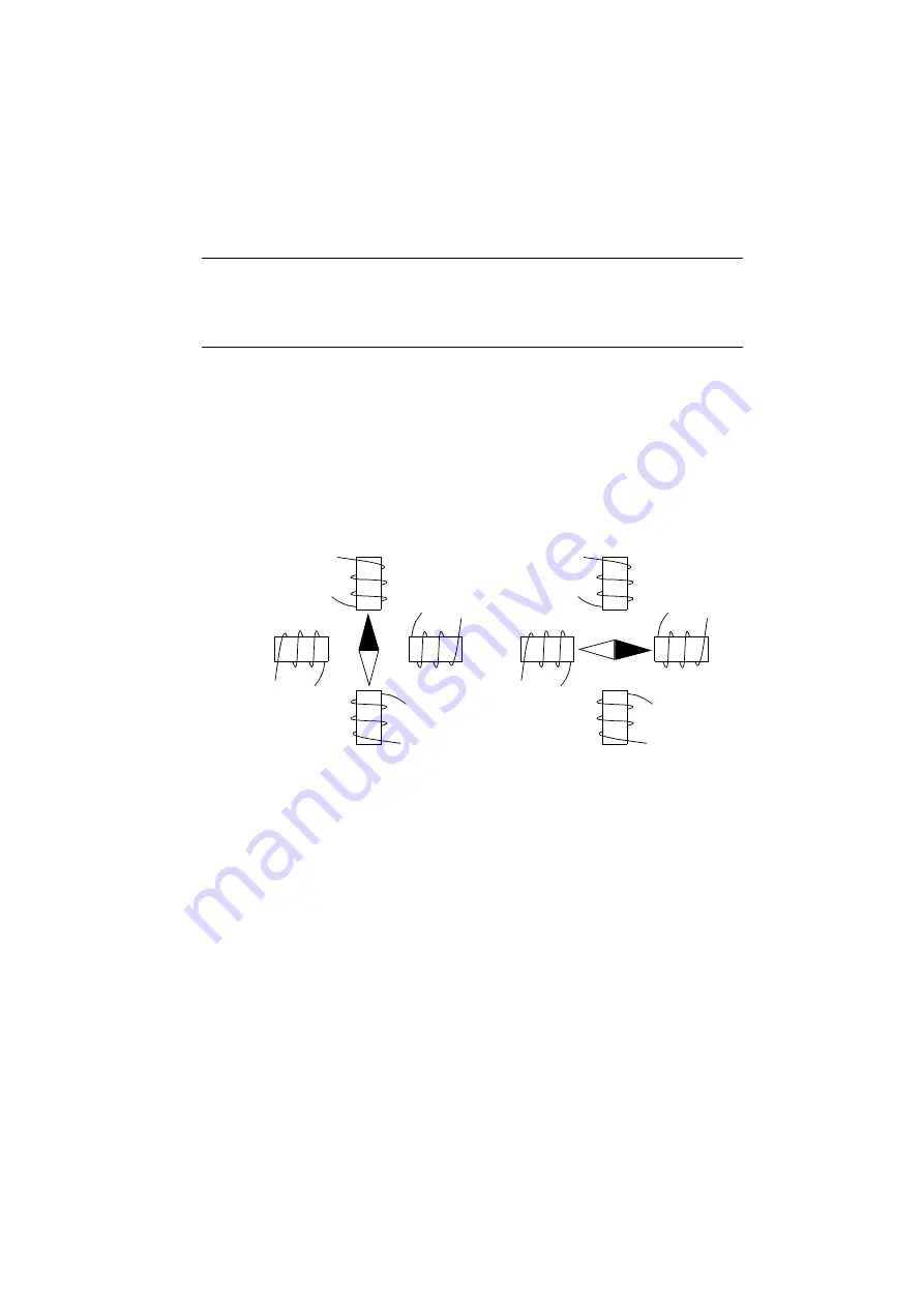
as illustrated in Fig. D.1.
Fig. D.1 Simplified concept of stepper motor operation
Although only 4 stator poles are shown above, in reality there are numerous tooth-like
poles on both the rotor and stator. For example, with a 24 step motor such as that
used in the ZST actuators positional increments (steps) of 15 degrees can be
achieved by switching the coils. If the current through one coil is increased as it is
decreased in another, the new rotor position is somewhere between the two coils and
the step size is a defined fraction of a full step (microstep).
The size of the microstep depends on the resolution of the driver electronics. When
used with the Thorlabs miniAPT motor controller,128 microsteps per full step can be
achieved, giving a total resolution of 3072 microsteps per revolution for a 24 full step
motor. In the case of the ZST actuators supplied with the miniAPT controller, further
mechanical gearing provides a higher effective angular resolution.
In practise, the mechanical resolution achieved by the system may be coarser than a
single microstep, primarily because there may be a small difference between the
orientation of the magnetic field generated by the stator and the orientation in which
the rotor shaft comes to rest.
N
S
on
on
N
S
on
on


