Thermo Scientific SOLA II Flare Скачать руководство пользователя страница 132

Appendix B 

Rotary Valve Service 

Assembly 

Where possible, apply a slight rotating action to the parts as they go over or 

through the O-Rings to help prevent any nicking or tearing of the new parts. 

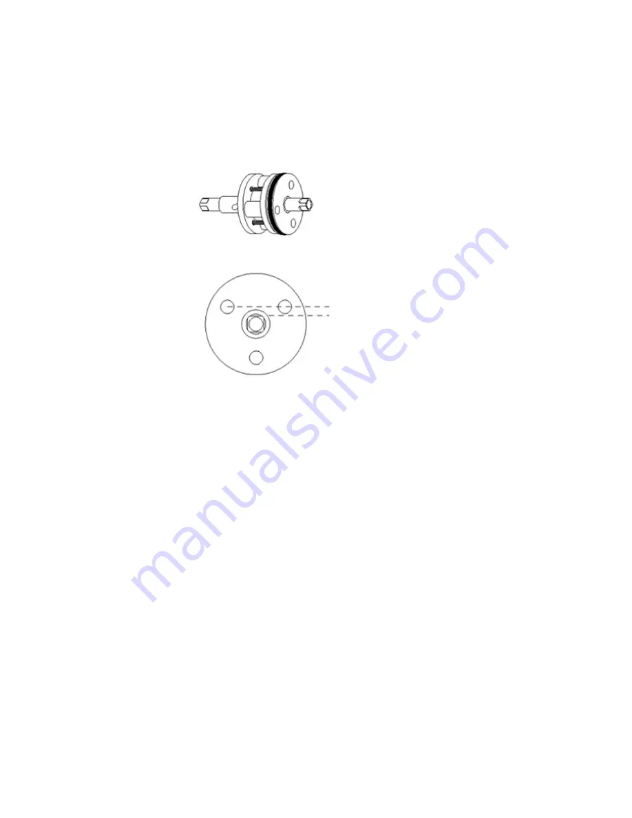
1. Being careful that the subassembly does not come apart, gently push the

O-Ring plate onto the drive shaft. Make sure that the threaded holes in

the plate are facing the subassembly.

Figure B–10. 

Figure B–11. 

2. Screw the slotted-head screws into the O-Ring plate, and push the drive

shaft into the O-Ring plate as far as it will go, as shown in Figure B–10.

3. Place the washers and bearing in the male end cap (thin washers in first,

as shown Figure B–9). One of the flats on the drive shaft lines up with a

line drawn between two of the holes in the O-Ring plate (Figure B–11).

4. Slide the subassembly onto the pins of the male end cap with this flat

lined up with the air inlet on the end cap.

5. Install the cylinder, sliding it over the subassembly and pressing the

male end cap into it.

6. Place the washers and bearing in the female end cap. Press the end cap

into the cylinder, making sure that the air inlet hole is in the same

orientation as the one in the male end cap.

7. Install the three end cap screws with the PEEK washers provided.
8. Replace the valve mounting hardware and air supply lines.

Thermo Scientific 

SOLA II Flare User 

Manual


B-10 

Содержание SOLA II Flare

Страница 1: ...SOLA II Flare Sulfur Online Analyzer User Manual PN 90 1312 0...

Страница 2: ......

Страница 3: ...SOLA II Flare Sulfur Online Analyzer User Manual PN 90 1312 0 Revision A...

Страница 4: ......

Страница 5: ...gistered trademarks of Watlow Electric Manufacturing Company VICI is a registered trademark of Valco Instruments Co Inc and VICI AG All other trademarks are the property of Thermo Fisher Scientific In...

Страница 6: ......

Страница 7: ...Thermo Scientific SOLA II Flare User Manual v Revision History Revision Level Date Comments A 03 2015 Initial Release per ERO 8626...

Страница 8: ......

Страница 9: ...Switching 1 4 Validation 1 5 Calibration 1 5 Principle of Operation 1 5 PUVF Detector 1 6 Pyrolyzer 1 6 Injection Valve 1 6 Mixing Chamber 1 7 Dual Measuring Range 1 7 Dual PMT Power Supplies 1 8 Spec...

Страница 10: ...I Flare Menus 3 5 Chapter 4 Operation 4 1 The Interface 4 1 Begin Analyzing 4 1 Suspending an Analysis 4 2 Injection Valve Failure Alarm 4 2 Chapter 5 Configuration 5 1 Analyzer Setup 5 1 Clock Setup...

Страница 11: ...8 1 Maintenance Schedule 8 1 Visual Inspection Cleaning 8 1 Leak Tests 8 2 Clean Air Leak Test 8 2 Sample Flow Leak Test 8 4 Clean Nitrogen Leak Test 8 5 Flow Rate Checks 8 6 The Rotary Valve 8 7 The...

Страница 12: ...Temperature Valves B 7 Two Position Air Actuator O Ring Replacement B 7 Disassembly B 7 Replacement B 9 Assembly B 10 Valve Alignment B 11 Rebuild the Assembly B 12 Appendix C TCP IP Bridge C 1 Hardwa...

Страница 13: ...X Purge Specifications F 3 Installation F 3 AC Power F 4 Alarm Signal F 5 Startup F 5 Shutdown F 7 Power or Purge Loss Shutdown F 7 Maintenance F 8 Timer Adjustment F 9 Appendix G PUVF Optical Bench...

Страница 14: ......

Страница 15: ...y it must not be performed until appropriate actions can be taken to ensure the safety of the equipment and personnel The procedures in this manual are not designed to replace or supersede required or...

Страница 16: ...on Failure to heed the following information may lead to equipment damage or injury to personnel Protective eyewear glasses with side shields or goggles as appropriate must be worn when servicing any...

Страница 17: ...tem enclosures are opened The AC power to the system must be free from noise surges sags and spikes for proper system operation AC power circuit breakers and wiring must be sized properly for the requ...

Страница 18: ......

Страница 19: ...ange the SOLA II Flare uses dual PMT photomultiplier tube power supplies and dual sample injection valves to achieve two independent measurement ranges The low measurement range is configured as 1 of...

Страница 20: ...limit on the low range of 100 200 ppm depending upon the final set up used Figure 1 1 Typical SOLA II Flare analytical oven flow diagram Set up and programming of the SOLA II Flare is easy using the...

Страница 21: ...amount of sample injected into the zero grade air carrier gas For gaseous samples a backpressure regulator allows the pressure sample volume to be held constant in the sample loop of the injection va...

Страница 22: ...level system Once the analyzer is in the high measurement range the increased sulfur level will not over range the analyzer detector and the sulfur level can be tracked during the flaring event If th...

Страница 23: ...are routed into the oven through a heat traced line The traced bundle enters through a hole in the oven and a heat shrinking boot typically provided by the system integrator The sample is mixed with a...

Страница 24: ...Thermo Scientific The pyrolyzer typically operates at a temperature of 1100 C 2012 F to oxidize sulfur without the need for a catalyst Figure 1 2 Pyrolyzer Injection Valve Using two sample injection...

Страница 25: ...100 1 dilution ratio The two injection valves allow for two completely separate measuring ranges in the PUVF Detector The Low Range uses a 10 port sample injection valve with a 100 sample loop and the...

Страница 26: ...t valves Valco w calibration valve in oven optional Dual PMT Power Supplies A dual PMT power supply is used in the SOLA II Flare This lets the user set the sensitivity of the PUVF detector and allows...

Страница 27: ...n each supply is adjusted using the corresponding PMT voltage adjustment to accommodate the desired range The analyzer is then calibrated and tested for each range During normal operation the supply v...

Страница 28: ...Flare automatic logging of analysis results and analytical parameters communication to SOLA II Flare via serial or TCP IP encapsulated Modbus enables remote diagnostics via modem SOLA Web Remote Inter...

Страница 29: ...e 1 5 Analyzer Sample Vent No backpressure may be applied and the PUVF Detector sample vent the vented gases will contain CO2 H2O and high levels of SO2 Sample The suggested sample input pressure is d...

Страница 30: ...0 75 1340 0 Valve complete 10 port for vapor samples 0 0 1 1 75 1332 0 Valve complete 6 port for vapor samples 0 0 1 1 75 1355 0 Rotor vapor sample 4 pt 1 1 2 0 45 1835 0 Rotor vapor sample low range...

Страница 31: ...be IP40 rated metallic cable glands Blanking elements or plugs used shall be in accordance with national standards Caution This product is extremely heavy Care must be taken at all times to avoid inj...

Страница 32: ...d Warning Installation of this instrument requires an external lockable electrical power isolation switch supplied by the customer If the optional X Purge unit is installed refer to Appendix F for imp...

Страница 33: ...Cal B The zero value 4 mA dc represents zero measured concentration in the sample Full scale 20 mA dc represents the measured concentration specified in High Range Other Outputs The following outputs...

Страница 34: ...robe and back to the switching panel as the normal flare sample Five pneumatic outputs from the SOLA II Flare can drive a sample select valve Flare Sample Low Gas Mid Gas High Gas Local Probe selectio...

Страница 35: ...Range 0 Local Low Cal A X Cal A 1 Local Low Cal B X Cal B 2 Local Mid Gas Cal A X Cal A 3 Local Mid Gas Cal B X Cal B 4 Local High Gas Cal B X Cal B 5 Probe Low Cal A X X X X X Cal A 6 Probe Low Cal...

Страница 36: ...o the following Sample system properly designed to condition control pressure flow temperature and particulate sample as required by system Sample system fast loop panel is installed as close as possi...

Страница 37: ...h is installed d Ensure the instrument is properly grounded e Inspect all electrical connections Terminals must be snug wire and cable plugs must be fully seated Perform a visual check for electrical...

Страница 38: ...oaded S L I I F 4 4 1 1 1 8 1 3 C o n f i g u r a t i o n L o a d e d Figure 3 1 c Verify that the configuration settings in the menus match the application data sheet or system logbook d See Suspendi...

Страница 39: ...s shipped with the instrument and adjust the pressure regulators to the appropriate settings 2 Apply power to the analyzer Note If the X Purge option is installed you must follow the instructions incl...

Страница 40: ...ample flow to the instrument and purge the sample from the unit using nitrogen 2 Turn off power to the analyzer 3 Allow the instrument to cool Caution Failure to allow adequate cooling time before ope...

Страница 41: ...Chapter 3 Start Up Shutdown Thermo Scientific SOLA II Flare User Manual 3 5 SOLA II Flare Menus Figure 3 2 Top level menu Figure 3 3 Configuration menu...

Страница 42: ...Chapter 3 Start Up Shutdown Thermo Scientific SOLA II Flare User Manual 3 6 Figure 3 4 Diagnostics Menu...

Страница 43: ...re 3 5 SCS Valve Select menu The SCS Controls section of the software allows you to manually manipulate the SCS This can be used 1 During commissioning to ensure the SCS is plumbed correctly 2 During...

Страница 44: ......

Страница 45: ...below the down arrow When the correct number is displayed press the button below the right arrow to enter the next digit 4 Repeat the process used to enter the first digit for the remaining digits 5 O...

Страница 46: ...e air to the sampling system pneumatic and allows only air to run through the burner and mixing chamber 3 To resume the analysis go to the Analyzer Mode menu and select Active A n a l y z e r M o d e...

Страница 47: ...combusted sample products The user can enter the rate of change that triggers this alarm The programmable range is from 1 to 50 V 30 seconds If the analyzer detects the programmed rate of change in UV...

Страница 48: ......

Страница 49: ...o n f i g u r a t i o n E n t E x i t Figure 5 1 Top level configuration menu Analyzer Setup 1 Access the submenus within the Analyzer Setup menu by pressing Enter C o n f i g u r a t i o n A n a l y...

Страница 50: ...es are typically used to smooth output data See the figure below A n a l y z e r S e t u p A v e r a g e T i m e E n t E x i t Figure 5 4 4 The average override is expressed as a percentage of change...

Страница 51: ...p 1 Access the Clock Setup menu to change the time and date C o n f i g u r a t i o n C l o c k S e t u p E n t E x i t Figure 5 7 2 Using a 24 hour format enter the time in hh mm ss C l o c k S e t u...

Страница 52: ...r RS485 COM 3 38400 19200 9600 4800 2400 or 1200 bps or select Disable M o d b u s S e t u p C O M 3 M o d b u s B a u d r a t e E n t E x i t Figure 5 11 3 Set the parity for COM 3 M o d b u s S e t...

Страница 53: ...ure 5 14 Note The SOLA II Flare is preconfigured with a standard injection time and rate 2 The injection time is the amount of time between sample injections The rate can be from 1 to 9999 seconds I n...

Страница 54: ...a Chamber Flow alarm enter the set point at which the low flow alarm for the flow measured at the detector chamber in the PUVF should activate The value can be from 0 to 1000 cc m A l a r m s S e t u...

Страница 55: ...r m E n t E x i t Figure 5 20 5 To set up a Lamp Voltage Rate of Change alarm enter the rate of change in lamp voltage at which the alarm should activate The value can be from 1 to 50 V per 30 second...

Страница 56: ...bleshooting of intermittent problems or user acknowledgment of an alarm A l a r m s S e t u p S t a t u s A l a r m s M o d e E n t E x i t Figure 5 24 Calibration Overview The analyzer requires a two...

Страница 57: ...he values would be Low cal value 0 00 ppm Low cal 555 560 kHz High cal value 100 00 ppm High cal 15 000 000 kHz The high calibration value needs to be as close as possible to the full range sulfur con...

Страница 58: ...Calibration Setup menu can be used to correct the calibration by moving the line without changing the slope Figure 5 28 Corrected calibration There are several calibration functions that can be perfo...

Страница 59: ...on standard to flow into instrument 2 Watch the instrument s display and wait for the sulfur value to stabilize 3 Access the Configuration Menu on the SOLA II Flare s display 4 Access the Calibration...

Страница 60: ...new high calibration At this point the current average of the detector signal is latched to correspond to the high calibration value concentration Adjusting the Reading If the reported value of the SO...

Страница 61: ...engineering unit related to the concentration entered for the calibration values ppm ppb or mg L C a l i b r a t i o n S e t u p C a l U n i t s E n t E x i t Figure 5 30 2 Enter which valve is perfor...

Страница 62: ...t u p L o w C a l A V a l u e E n t E x i t Figure 5 33 5 Enter which valve is performing the Cal B injection V1 or V2 C a l i b r a t i o n S e t u p C a l B I n j e c t V a l v e E n t E x i t Figur...

Страница 63: ...d associate it to the High Cal A value C a l i b r a t i o n S e t u p R e c a l i b r a t e A H i g h E n t E x i t Figure 5 37 9 This step will associate the response of the detector to the Low Cal...

Страница 64: ...e t u p R e c a l i b r a t e B L o w E n t E x i t Figure 5 41 13 This step moves the calibration line so the reading matches the user desired reading for Cal B C a l i b r a t i o n S e t u p A d j...

Страница 65: ...lidation Setup Validation setup creates an automatic sequence to go through the stages that allow the user to select which pneumatic outputs and calibration are used Table 2 1 shows the validation req...

Страница 66: ...o n S e t u p D a i l y V a l i d a t i o n E n t E x i t Figure 5 48 3 Enter the time of day hh mm ss that the SOLA II Flare is to begin the automatic validation process V a l i d a t i o n S e t u...

Страница 67: ...Low Cal A 7 Probe Low Cal B 8 Probe Mid Cal A 9 Probe Mid Cal B 10 Probe High Cal B V a l i d a t i o n S e t u p S t e p 1 S e l e c t i o n E n t E x i t Figure 5 50 5 Enter the number of minutes 0...

Страница 68: ...o n S e t u p S t e p 6 T i m e E n t E x i t Figure 5 53 4 20 mA Range Setup Each calibration is configured to use a unique range for the 4 20 mA output The low end of the range 4 mA always correspo...

Страница 69: ...nge 4 t o 2 0 m A R a n g e s H i g h R a n g e T i m e o u t E n t E x i t Figure 5 56 4 Enter the switch hysteresis value a percentage of value change needed to switch ranges 4 t o 2 0 m A R a n g e...

Страница 70: ......

Страница 71: ...l through the alarms automatically S L I I F 4 4 1 1 1 8 1 3 V i e w A c k A l a r m s E n t E x i t Figure 6 1 Press Ack on the system display to acknowledge the alarm V i e w A c k A l a r m s I n j...

Страница 72: ......

Страница 73: ...he Input Output Test menu consists of four groups of submenus Set Outputs Menu View Mux Analogs 4 20 mA Inputs and View Digital Inputs D i a g n o s t i c s I n p u t O u t p u t T e s t E n t E x i t...

Страница 74: ...select Solenoid 5 Generic output for sample control Solenoid 6 Generic output for sample control Solenoid 7 Generic output for sample control Solenoid 8 Generic output for sample control Chn 1 4 20 Pr...

Страница 75: ...s E n t E x i t Figure 7 4 Following are the analogs in the order they appear within menu 1 ADC 0 Lamp V 2 ADC 1 Chamber Flow 3 ADC 7 Pressure 4 ADC 9 PMT V 5 ADC 10 Chamber T 6 ADC 11 Ambient T View...

Страница 76: ...ultaneously Zero 0 denotes open One 1 denotes closed CPU Digital In Dip Switches Displays the positions of dip switches located in the motherboard dip switches are used to indicate options installed I...

Страница 77: ...i e w P a r a m e t e r s E n t E x i t Figure 7 7 T S R e a d i n g 0 0 0 1 H o u r s M I N 4 3 1 2 M A X 4 2 0 1 4 4 5 5 Figure 7 8 Parameter name Current Value Minimum Value Maximum Value Clock Th...

Страница 78: ...kHz The frequency proportional to the PMT output normalized to the gain of 100 also displays the gain currently selected PMT Signal kHz The actual frequency proportional to the PMT output also displa...

Страница 79: ...Note Auto gain defaults to ON during normal operation PMT Signal Gain Select the amplifier gain 1 2 5 10 20 50 100 Note The selection is only valid when auto gain is turned OFF Test Gains Place the ga...

Страница 80: ......

Страница 81: ...hs Visually inspect and clean the instrument Check the instrument flow rates as explained later in this chapter Replace the valve body according to Appendix B Annually Test the instrument for internal...

Страница 82: ...egulator off All regulators for clean air nitrogen and sample should be set to zero psig Leave the power on as it will be needed during the leak test to actuate valves Clean Air Leak Test 1 Clean air...

Страница 83: ...complete b If the pressure falls then either the quartz tube is cracked and must be replaced or the fittings holding the tube at the top of the pyrolyzer need to be tightened Care must be taken when t...

Страница 84: ...clean nitrogen regulator located in the pneumatic section of the SOLA II Flare to zero psig Set the 1 8 inch four port range select valve to the Off position using the input output test under the dia...

Страница 85: ...cap remains continuous replace the tubing 11 Turn V3 On in the Diagnostics menu refer to step 2 This will push the external nitrogen source through the 10 port valve Turn the external source of nitrog...

Страница 86: ...ously disconnected tubing Flow Rate Checks Figure 8 1 Three way valve for measuring flow rates 1 Obtain a precision flow measurement instrument such as a bubble meter 2 Ensure that all pressure regula...

Страница 87: ...or to obtain the required flow 13 Turn the Meas Clean Air 3 three way valves to point up for normal operation 14 Restart the analyzer according to Chapter 4 The Rotary Valve For detailed instructions...

Страница 88: ...he system Replacing the Pyrolyzer Heater Warning The pyrolyzer can be extremely hot even after power is turned off Use extreme care to prevent burns The pyrolyzer heater is enclosed in the pyrolyzer h...

Страница 89: ...O ring screws washers HA 101812 2 Ferrule 1 4 graphite 1 Follow the Maintenance Shutdown Procedure to shut down the analyzer system Allow the system to cool completely 2 Carefully remove the two samp...

Страница 90: ...emove the pyrolyzer housing lid 8 Gently lift the lid off and set it aside Note The pyrolyzer tube insulation and Kaowool insulation will be attached to the lid Carefully lift all of it out to avoid d...

Страница 91: ...insulation aside You will need it later Figure 8 5 Heater wires and thermocouple Figure 8 6 Remove the fiberglass insulation 10 Loosen the fittings around the heater wires and remove the wire sleeves...

Страница 92: ...ater into housing 14 Feed the two heater wires through the two fittings on the other side of the housing Figure 8 8 Heater wires fed through fittings 15 Slide the wire sleeves onto the heater wires Ti...

Страница 93: ...ation to make the hole Remove the bit and then carefully feed the thermocouple tube through the stainless steel fitting on the housing Tighten the thermocouple fitting to secure it to the housing Figu...

Страница 94: ...er housing If necessary replace it and apply a lubricant compound such as Dow Corning 111 around it Figure 8 13 Pyrolyzer housing O ring 20 Gently slide the lid into the housing Note The pyrolyzer tub...

Страница 95: ...he pyrolyzer housing to the oven enclosure using the screws removed earlier two mounting screws on top of housing two on bottom 24 If necessary reconnect the wires from the oven temperature switches 2...

Страница 96: ...ft all of it out of the housing Figure 8 15 Housing lid with insulation and pyrolyzer tube attached 2 To remove the existing pyrolyzer tube unscrew the two fittings from the lid while holding the tube...

Страница 97: ...rrules and one of the fittings removed earlier to each of the pyrolyzer tube ends Figure 8 18 Reattach the ferrules and fittings 6 Gently slide the lid back into the housing and secure it using the sc...

Страница 98: ...tart up No power Ensure instrument is connected to the proper source Digital electronics Ensure boards are seated properly and interconnecting cables are in place Replace boards one at a time to isola...

Страница 99: ...ature limits Measure ambient and purge air temperatures and correct as necessary Thermistor not positioned correctly Reposition Thermistor Inject Temperature alarm displayed1 Instrument is starting up...

Страница 100: ...tronics and replace if necessary No 4 20 mA dc output current Incorrect or damaged wiring2 Check wiring diagrams to ensure 4 20 mA dc signal connected to proper terminals with correct polarity Check f...

Страница 101: ...Thermo Scientific for specific instructions If it becomes necessary to contact Thermo Scientific with software or hardware problems please have information on the ranges and installed options availab...

Страница 102: ...l or workmanship and which are reported to Thermo Scientific within the warranty period as provided above This right to replacement shall be Buyer s exclusive remedy against Thermo Scientific Thermo S...

Страница 103: ...arts are considered consumable items and are not covered under the warranty Injection valve and associated parts Inline filter UV lamp Combustion tube quartz Pyrolyzer O Ring silicone Combustion tube...

Страница 104: ......

Страница 105: ...es basic operating instructions and default configuration settings For complete operating information and troubleshooting refer to the EZ ZONE PM PID Controller user s manual Hardware Setup The EZ ZON...

Страница 106: ...ayed as a percentage or when the open loop set point is displayed This LED indicates the status of a profile When lit a profile is running When flashing a profile is paused Indicates communication act...

Страница 107: ...tom Home Page and perform other tasks that do not have an effect on the control when running Home Page The page that is displayed when the control is initially powered up Parameters for the EZ ZONE PM...

Страница 108: ...C The minimum value of the closed loop set point range High Set Point 1150 C The maximum value of the closed loop set point range Set Point Open Limit Low 100 0 The minimum value of the open loop set...

Страница 109: ...Hysteresis 2 C Alarm Logic Open On Alarm The output condition during an alarm state Alarm Sides Both Both high and low sides can trigger the alarm Alarm Latching Non Latching Alarm Blocking Off Alarm...

Страница 110: ...ime delay for toggling between channel 1 and channel 2 User Settings Save None User Settings Restore None Table A 9 Pyrolyzer settings Operations Page Analog Input 1 Parameter Description Display Soft...

Страница 111: ...he control mode currently in effect Possible displays listed below Off Auto Manual Heat Power The current heat output level Cool Power The current cool output level Closed Loop Set Point The set point...

Страница 112: ...he process value needs to be this far into the On region before the output turns on Cool Proportional Band 14 C The PID proportional band for the cool outputs Cool Hysteresis 2 C The process value nee...

Страница 113: ...Page Instance ID 1 Table A 15 Pyrolyzer settings Factory Page Custom Setup 3 Parameter Default Comment Display Software Display Software Parameter Autotune The parameter that will appear in the custom...

Страница 114: ...hermocouple RTD Leads 2 The number of leads on the RTD wired to this input Units Process The type of units measured by the sensor Scale Low 0 00 The low scale for process inputs Scale High 20 00 The h...

Страница 115: ...to last open loop set point entered by user Input Error Failure Off When an input error switches control to manual mode controller sets output to 0 Fixed Power 0 0 Open Loop Detect Enable No Open Loo...

Страница 116: ...power output will never be less than the value specified and will represent the value at which output scaling begins Output High Power Scale 70 The power output will never be greater than the value s...

Страница 117: ...ate Alarm Sides Both Both high and low sides can trigger the alarm Alarm Latching Non Latching Alarm Blocking Off Alarm Silencing Off Alarm Display On An alarm message will display when an alarm is ac...

Страница 118: ...ime delay for toggling between channel 1 and channel 2 User Settings Save None User Settings Restore None Table A 24 Oven settings Operations Page Analog Input 1 Parameter Description Display Software...

Страница 119: ...t set point that will be used by autotune Autotune No Closed Loop Set Point 110 0 C The set point the controller will automatically control to Idle Set Point 25 0 C The closed loop set point that can...

Страница 120: ...e Display Software Parameter Active Process Value The parameter that will appear in the custom Home Page Instance ID 1 Table A 29 Oven settings Factory Page Custom Setup 2 Parameter Default Comment Di...

Страница 121: ...clearance Write Security 0 The level of write security clearance Locked Access Level 1 Rolling Password Off User Password 63 Administrator Password 156 The Lockout Menu Each menu has a security level...

Страница 122: ......

Страница 123: ...ve As supplied all surfaces are clean and free of contaminants and must be kept clean to prevent valve damage Open ports and fittings cause unnecessary risk of particulate matter entering the valve an...

Страница 124: ...ead the entire procedure before beginning Figure B 1 Rotary valve disassembly As this figure illustrates the valve can be disassembled for cleaning and or rotor replacement without removing the loops...

Страница 125: ...alve body and the metal of the rotor or any tool used is likely to cause damage Carefully withdraw the rotor from the valve body with the magnet Once the rotor is removed note the orientation of the r...

Страница 126: ...or of the valve to remove any loose residue 3 Blow with clean compressed gas to remove any lint left by the swab 4 Visually inspect the interior of the valve body The conical surface should appear hig...

Страница 127: ...B 4 2 Insert the rotor into the valve body being careful that the tab does not touch the polished interior of the valve body Make sure the rotor tab Figure B 4 is fully inserted into the slot in the d...

Страница 128: ...lve WT or UWT series is used at less than 300 C it may become sticky or difficult to turn This tendency can usually be eliminated by repeating the conditioning procedure that is initially done at the...

Страница 129: ...tasks described in this section 9 64 hex driver 3 8 open end wrench 3 16 screwdriver An awl or small jeweler s screwdriver Silicone lubricant such as Dow Corning DC 111 Lint free tissues and a clean s...

Страница 130: ...the way off If the bearing and washers fall out set them aside 6 Repeat the procedure with the actuator inverted so that the cylinder slides loose from the male end cap Remove the cylinder Figure B 7...

Страница 131: ...he O Ring plate The internal end cap O Rings are easier to access if the washers and bearing are removed Follow the steps below 1 Use a small screwdriver or awl to remove the old O Rings being careful...

Страница 132: ...rs and bearing in the male end cap thin washers in first as shown Figure B 9 One of the flats on the drive shaft lines up with a line drawn between two of the holes in the O Ring plate Figure B 11 4 S...

Страница 133: ...h the actuator from one position to the other several times to make sure that the play in the coupling mechanism has been absorbed 2 Visually inspect the valve body cutout to determine if the rotor pi...

Страница 134: ...ugh the three small O Rings Pressing the plate in dislodges the O Rings do not press the plate in 6 The two bearing plates are identical except that one has three countersunk holes to accept the subas...

Страница 135: ...Appendix B Rotary Valve Service Figure B 12 Exploded view of two position actuator Thermo Scientific SOLA II Flare User Manual B 13...

Страница 136: ......

Страница 137: ...10 100 Base T cable Figure C 1 TCP IP Ethernet bridge board P N 55 1228 0 newer models Software Configuration As shipped the Bridge defaults to an IP address of 00 00 00 00 At power up with an IP add...

Страница 138: ...the IP address required for configuring a workstation or DCS to query the SOLA II Flare On the TCP IP Modbus frame the unit ID must always be set to 1 Figure C 2 Example display with DHCP server pres...

Страница 139: ...ister Function 15 Set Multiple Coils Function 16 Set Multiple Holding Registers Note Register numbering follows the standard Modbus encoding The actual number sent in the function query is one less th...

Страница 140: ...d future usage 11 Reserved future usage 12 Reserved future usage 13 Reserved future usage 14 Reserved future usage 15 Reserved future usage 4 0065 Raw Detector Signal 0 to 21000 KHz recommended histor...

Страница 141: ...puter hard drive Remove the disk from the drive and store in a safe place 2 Click on fdcws l4p to open the workstation through Lookout 3 The workstation is configured to connect to the analyzer using...

Страница 142: ...us Ethernet a Set the IP address to the value assigned to the Bridge The required IP address depends on the configuration of the Modbus Ethernet Contact the person responsible for this network to obta...

Страница 143: ...communication with the analyzer Depending on the PC used these numbers may need to be increased Figure E 3 Workstation Operation Using the operation application with Lookout enables you to monitor and...

Страница 144: ...sola directory with subdirectories that match the year month and date for the analysis Figure E 4 Workstation main screen As shown in Figure E 4 the main screen is divided into several operating secto...

Страница 145: ...the right end of the bar turns on to indicate that viewed data is historical rather than real time Clicking the lower indicator of the two turns that indicator green and returns the plot to real time...

Страница 146: ...ing Diagnostics displays a list of current values for several status monitors and a trend chart showing historical values These status values are useful for troubleshooting Figure E 5 Diagnostic Trend...

Страница 147: ...ure E 6 Diagnostic Signals SCS Controls Clicking SCS Control displays a set of selections that allow the user to control the SOLA II Flare validation range Once a user selects an option the workstatio...

Страница 148: ......

Страница 149: ...ins its timed cycle Typically the time delay is used to ensure that at least four volumes of air are exchanged in the enclosures before power is applied to the system The number of exchanged volumes m...

Страница 150: ...e allowed to cool for at least 140 minutes before opening the oven door Caution Failure to allow adequate cooling before opening the oven can lead to injury of personnel or damage to equipment Note Ca...

Страница 151: ...ndividual system X Purge pressure Minimum 10 psig Oven air pressure Minimum 10 psig or as specified in instrument application notes or system log books Oven door Closed tightly Electronic housing door...

Страница 152: ...power must be free of spikes sags surges or electrical noise AC power to any system using the X Purge is connected directly to the X Purge unit rather than the analyzer The X Purge unit controls the...

Страница 153: ...horoughly tested for leaks Caution Do not open the explosion proof X Purge enclosure in a hazardous area even when de energized unless area has been properly tested and is known as being free from exp...

Страница 154: ...e X Purge housing unless power is removed from the X Purge or the area is known to be non hazardous If the unit does not apply power to the analyzer system after the required length of time check for...

Страница 155: ...nalyzer system When the power or purge pressure is restored the X Purge begins the purge timer After the required purge time is achieved the X Purge unit applies power to the analyzer system The X Pur...

Страница 156: ...Caution Do not open the explosion proof housing for the X Purge unless the area is known to be non hazardous Caution Do not leave the Normal Bypass switch in the Bypass position after maintenance is c...

Страница 157: ...n received from Thermo Scientific Caution If the timer setting is too short the analyzer system is not purged adequately before power is applied This can result in equipment damage and injury to perso...

Страница 158: ......

Страница 159: ...Appendix G PUVF Optical Bench Figure G 1 Optical bench assembly exploded diagram PN TE 57P713 1 Thermo Scientific SOLA II Flare User Manual G 1...

Страница 160: ......

Страница 161: ...dous Substances Tables The English and Chinese versions of the Toxic and Hazardous Substances tables are shown below Table H 1 SOLA II Flare toxic hazardous substances table Thermo Scientific SOLA II...

Страница 162: ......

Страница 163: ...rces tab Table I 1 Technical bulletins TB Title TB 0417 001 Replacing a Watlow Series 93 Temperature Controller with a Watlow EZ ZONE PM6 Series Controller TB 0417 003 Increasing the Lifetime of the P...

Страница 164: ...Thermo Fisher Scientific 81 Wyman Street P O Box 9046 Waltham Massachusetts 02454 9046 United States www thermofisher com...

Отзывы: