background image

49


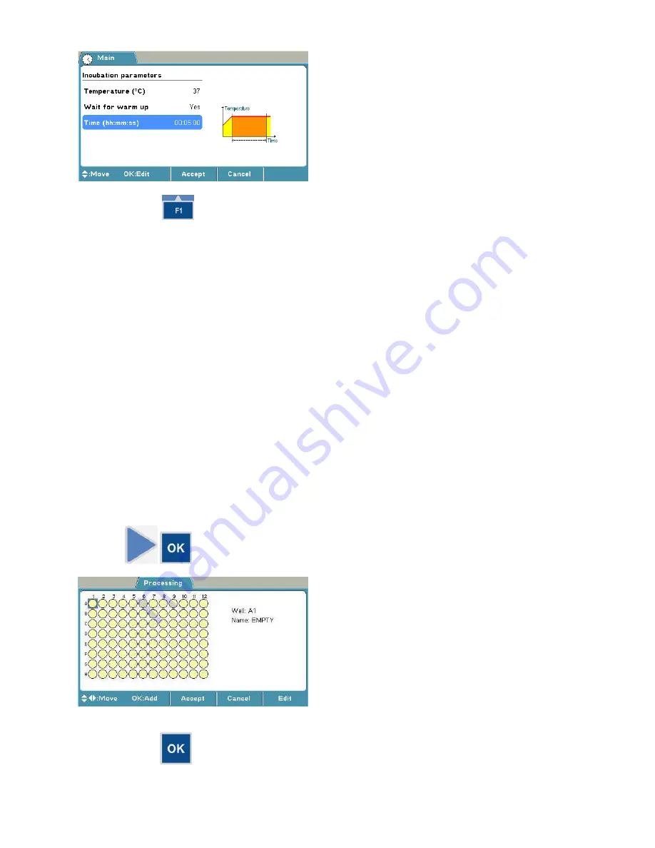
6.  Press the 

F1

 key to accept the incubation parameters. 


Programming a plate layout 

You can start filling the plate layout on any of the wells of the plate. You start the fill procedure from 
the well marked with a 

blue

 square. You can start filling a series of samples by pressing the 

OK


button in the highlighted well. You can edit and delete a single well with the 

Edit

 function. 

The plate layout parameters have to be set prior to measurement. The parameters cannot be 
changed after measurement. 

In this example, 

  a blank sample, 

  Calibrator 1 (Conc. 1), 

  Calibrator 2 (Conc. 2), 

  Calibrator 3 (Conc. 3), 

  a control sample, and 

  91 unknown samples 

are programmed. 

To create the plate layout of this example protocol: 

1.  Select the 

Plate layout

 row in the 

Processing

 menu using the 

Right


arrow key. Then press the 

OK

 button to open the 

Layout

 window. 


2.  Press the 

OK

 button to start filling the plate from well A1. 

Содержание Multiskan FC

Страница 1: ...Thermo Scientific Multiskan FC User Manual Rev 2 2 Cat No N07710 ...

Страница 2: ...equires uninterrupted power supply in order to operate correctly Thermo Fisher Scientific has no responsibility whatsoever for system malfunctions arising from power failures Warranty The Thermo Scientific Microplate Instrumentation products are fully guaranteed against defective parts and materials including defects caused by poor workmanship for a period of one year from the date of delivery The...

Страница 3: ...s ordering information Read the manual in its entirety before operating the instrument Keep the user manual for future reference The user manual is an important part of the instrument and should be readily available during use of the instrument Keep the user manual together with the instrument in case you distribute it onwards For more information For PC software related issues refer to the Thermo...

Страница 4: ...lf Power ON Power OFF The plate carrier may come out risk of operational failure or damage Warning Hot plate risk of burns Serial number Catalog number Date of manufacture Consult instructions for use WEEE symbol This product is required to comply with the European Union s Waste Electrical Electronic Equipment WEEE Directive 2012 19 EC A black label with the following text Figure 11 CAUTION WARNIN...

Страница 5: ... electric shock Warning Biohazard risk Warning Hot plate risk of burns Risk of injury to the user s Caution Risk of damage to the instrument other equipment or loss of performance or function in a specific application Note Marks a hint important information that is useful in the optimum operation of the system or an item of interest ...

Страница 6: ...Front view 16 Back view 16 Side view 17 USB memory device port 17 Incubator 18 Shaker 18 Internal memory 18 Chapter 4 Operating the Internal Software 18 Display and keys for navigating and editing 18 Keys Action 19 Chapter 5 Menus and Parameters 20 Main menu 20 Protocol 22 Plate format parameters 23 Measurement parameters 24 Filters 24 Measurement modes 24 Shaking parameters 24 Incubation paramete...

Страница 7: ...hutdown 62 Chapter 11 Modifying Settings 62 System settings 62 Setting the date 62 Changing the language 62 Filters 63 Introducing a filter to the internal software 63 Removing a filter 64 Printer 64 Startup 64 Chapter 12 Emergency Situations 65 Handling emergency situations 65 Chapter 13 Maintenance 65 Regular and preventative maintenance 65 Maintenance checklist 65 General 66 Immediate 67 Cleani...

Страница 8: ...al stresses 82 Chapter 16 Ordering Information 83 List of filters 83 List of spare parts and accessories 83 List of Thermo Scientific plates 84 Verification tools 84 Appendix A System Log 85 Appendix B Certificate of Decontamination 86 ...

Страница 9: ...d strips in 96 well plate formats and optionally microplates in 384 well plate formats that meet the ANSI SBS standards The Multiskan FC as standalone instrument or with SkanIt Software can be used in research or routine test laboratories by professional personnel The Multiskan FC is part of the analyzing system used by the end user who therefore is responsible for validation of the whole system f...

Страница 10: ...weighs 8 5 kg 18 7 lbs and care must be taken when lifting it Unpacking How to unpack Move the packed instrument to its site of operation To prevent condensation the instrument should be left in its protective plastic wrapping until the ambient temperature has been reached Unpack the Multiskan FC instrument and accessories carefully with the arrows on the transport package pointing upwards Place t...

Страница 11: ...or cables covers and so on there is sufficiently room behind the instrument to enable disconnecting the device there is enough clearance in front of the instrument for the plate carrier to come out freely the ambient air is clean and free of corrosive vapors smoke and dust the ambient temperature range is between 10 C 50 F and 40 C 104 F the humidity is low so that condensing does not occur relati...

Страница 12: ...fastening the transport lock 3 Pull the transport lock bar out Figure 5 Figure 5 Pulling the transport lock out 4 Keep the transport lock bar and tag Figure 6 for future relocation or transportation of the instrument ...

Страница 13: ... not touch the filters with your bare hands Caution When installing the filter wheel do not touch any other mechanical or electronic part 2 Place the filter wheel into the filter slot so that the filter wheel numbers 1 8 face outwards Figure 8 A magnet locking mechanism will automatically lock the wheel in the correct position and the optical filter position sensor will make sure the correct filte...

Страница 14: ... OFF switch Figure 9 at the back of the instrument is in the OFF O position 2 Connect the power supply cable to the power supply connector and plug in the instrument 3 Connect the power supply to a correctly installed line power outlet with a grounded conductor Figure 9 Figure 9 Connecting the power supply cable Connecting to a computer If you are using a computer with the Multiskan FC connect the...

Страница 15: ...es properly The instrument starts the measurement After the measurement the plate carrier comes out No error messages should appear on the display 5 Press the F2 key to close the result table 6 Press the Left arrow key twice to return to the Main menu Settings after installation If you want to change the language or add additional filters to the filter wheel modify the required settings in the Set...

Страница 16: ...r 3 Multiskan FC Main Parts Front view The front view of the Multiskan FC instrument is shown in Figure 10 Figure 10 Multiskan FC front view Back view The back view of the Multiskan FC instrument is shown in Figure 11 Lamp and filter wheel chamber cover Measurement chamber door Keypad Display ...

Страница 17: ... equipped with a USB port for an external memory device Figure 11 You can transfer measurement data to the PC and assay protocols from an instrument to another with the USB memory device Cooling outlet USB port for memory device Type label ON OFF switch Power supply connector Warning marking USB port for PC USB port for printer Lamp and filter wheel chamber cover open Plate carrier OUT ...

Страница 18: ...ime During measurement the background temperature is used if the protocol incubation temperature Main Incubation is not in use No When the protocol temperature is set it is used as the incubation temperature during measurement After measurement the background temperature is taken into use again Background incubation is also possible during kinetic measurements Warning The incubator thermal plates ...

Страница 19: ...lding down the arrow key continuously Press the OK button to select and edit the highlighted item Use the character keys to enter numerical data and text and µ are found under the 1 key The CLEAR C key is used to delete written text or numbers Use the F1 F3 keys to select the corresponding action from the info text bar Figure 14 The information on the info text bar is updated according to the acti...

Страница 20: ...he reading process Data from the plate in progress is lost It can also be used to terminate the possible computer remote control Chapter 5 Menus and Parameters This section describes the menus and the relevant main parameters of the internal software for creating and editing protocols The internal software includes the Main Processing Results and Settings menus The menu tree is displayed in Table ...

Страница 21: ...cked when the run measured data for the protocol exists After the measurement the plate format measurement shaking and incubation parameters cannot be changed For more information refer to Chapter 6 Starting Ready made Protocols Table 3 Main parameters Main Protocol Protocol Created Modified Runs Plate format 96 Wells 384 Wells Measurement Filter 1 nm No filter 405 1 450 2 620 3 Filter 2 nm No fil...

Страница 22: ...an also open a particular run of the protocol in question protocol with measured data with the Menu function Also the runtime is shown on the Protocol row For more details on opening a protocol refer to Opening a new protocol The maximum number of protocols is 99 Table 4 Protocol structure Protocol 1 Run 1 Run 2 Protocol 2 Run 1 Run 2 Run 3 A measured run of a protocol includes run data and protoc...

Страница 23: ... 6 Starting Ready made Protocols and Chapter 7 Protocol Creation Plate format parameters You can select the plate format 96 or 384 in the Plate format window Note The 384 format is only available if the instrument configuration supports 384 well plate measurements Note Use only plates manufactured according to ANSI SBS standard dimensions The dimensions of the available plates are given in Table 5...

Страница 24: ...Fast mode produces fast results with a slightly narrower linear absorbance range than with the Normal mode Number of readings sets the number of measurements per well One means that each well is measured only once and two or more means that the measurement is repeated kinetic The number of readings can be anything between 1 and 100 If the Number of readings is higher than 1 the measurement is cons...

Страница 25: ...ts When the background incubation Settings Startup Temperature temperature is set the incubation temperature is activated once the instrument is switched on Note that the cooling of the incubation chamber takes time If you get the warning of Temperature is not changing it means that the incubator chamber is cooling slowly It is possible to start the run despite of the warning message in case the i...

Страница 26: ...layout Well A1 Name EMPTY Well type Blank Calibrator Control Unknown Empty Fill direction Down Right Replicate direction Down Right Number of 1 Replicates 1 Depending on the level of the internal software the FILE key opens a list of actions possible for the current protocol You can start filling the plate layout on any of the wells of the plate You start the fill procedure from the well marked wi...

Страница 27: ...the number of samples belonging to the group for example the number of different calibrators or the number of different unknown samples in Number of You define the number of replicates for each sample type in Replicate Note The Replicate number is the same for samples for example for different controls when using Add series starting from the well programming Use the F3 Edit key to program each sam...

Страница 28: ...Processing Preprocessing Preprocessing Pre Calculation No Mea1 Mea2 Mea1 Mea2 Mea1 Mea2 Mea1 Mea2 Mea2 Mea1 Mea2 Mea1 Kinetic Type No Average rate Kinetic rate s min Ignore from beginning 0 Ignore from end 0 Maximum rate Kinetic rate s min Ignore from beginning 0 Ignore from end 0 Window 2 Reaction Undefined Increasing Decreasing Time to maximum rate Kinetic rate s min Ignore from beginning 0 Igno...

Страница 29: ...ions possible for the current protocol Precalculations Precalculation is used in the context of dual two wavelength measurements when Filter 1 main filter and Filter 2 reference filter are defined in the Main menu The purpose of the precalculation is to merge the data from the two measurements into one data set which can then be further processed for example using kinetic calculations or a curve f...

Страница 30: ...always calculated per second but if you select per minute the time is automatically converted to minutes after the calculations Ignore from beginning Ignores a defined number of points readings counted from the first reading Ignore from end Ignores a defined number of points readings counted from the last reading Maximum rate If the maximum rate is selected the software searches the data for the m...

Страница 31: ...oftware searches for the maximum decreasing rate The rate is shown as a positive number If no decreasing rate is found the result is NaN not a number Kinetic rate Select to view the results in either seconds s or minutes min The kinetic rate is always calculated per second but if you select per minute the time is automatically converted to minutes after the calculations Ignore from beginning Ignor...

Страница 32: ...or this setting Undefined Searches for the absolute maximum rate and returns the corresponding time Increasing Searches for the maximum increasing rate and returns the corresponding time If no increasing rate is found the result is NaN not a number Decreasing Searches for the maximum decreasing rate and returns the corresponding time If no decreasing rate is found the result is NaN not a number Ig...

Страница 33: ... positive or negative and returns the corresponding time Increasing Searches for the increasing defined change in signal and returns the corresponding time If no increasing rate is found the result is NaN not a number Decreasing Searches for the decreasing defined change in signal and returns the corresponding time If no decreasing rate is found the result is NaN not a number Baseline readings The...

Страница 34: ...Ignore from beginning Ignores a defined number of points readings counted from the first reading Ignore from end Ignores a defined number of points readings counted from the last reading Calculation parameters You can define the calculation parameters in the Calculation window The plate layout parameters have to be set prior to measurement The parameters cannot be changed after measurement The ava...

Страница 35: ...inear Logarithmic Meas Transfor Linear Logarithmic Extrapolation Yes No Four parameter logistic Cubic spline Conc Transfor Linear Logarithmic Meas Transfor Linear Logarithmic Point to point Conc Transfor Linear Logarithmic Meas Transfor Linear Logarithmic Factor Value 1 000 Depending on the level of the internal software the FILE key opens a list of actions possible for the current protocol Curve ...

Страница 36: ...imum number of calibrators for this fit type is five yi ai bixi cixi 2 dixi 3 Only the means of the measured calibrator replicates can be used not the individual replicate values Extrapolation is not available for the cubic spline fit type Point to point The point to point method connects the adjacent response concentrations coordinates that is the calibration points together using a straight line...

Страница 37: ...Interpretation 2 Enter class in free text field Interpretation 3 The pop up menu appears when you press OK Depending on the level of the internal software the FILE key opens a list of actions possible for the current protocol Interpretation classification can be used in a qualitative assay a run where no absolute concentration is calculated and it can also be used for a quantitative assay a run wh...

Страница 38: ...sult in the category of higher than Limit 1 but less than Limit 2 for example Pos Interpretation 3 is a typed name for the sample result in the category of higher than Limit 2 for example High pos The interpretation limits can be entered with an editor The editor contains the following items Sample You can select a sample to be used for a limit calculation The Sample types can be blank BLA Calibra...

Страница 39: ... program rules for quality control and thereby ensure that the assay works as expected You can set a maximum of four QC rules per protocol Table 11 Processing parameters Quality control Processing Quality control Quality control Enable quality control Yes Rule 1 Rule 2 Rule 3 Rule 4 No Depending on the level of the internal software the FILE key opens a list of actions possible for the current pro...

Страница 40: ... menu You can view the results of a measured run assay in several formats in the Results menu depending on the protocol settings in the Processing menu raw data in list and table format calculated results in list and table format and graphs calibration and kinetic curves The assay data that is linked to the protocol consists of raw data and all the information needed for calculations programmed in...

Страница 41: ...ocessed Concentrations for extrapolated data cannot be calculated when extrapolation is disabled The qualitative range is undefined If previous calculation results are NaN Note Blank subtraction is made automatically if the plate layout includes blanks The blank used in the calculations is always an average of the blanks included in the layout Note The results of precalculations are not available ...

Страница 42: ... calibration curve You can disable and enable calibrator replicates from the curve by pressing the OK button in the Calibration curve window If the user enables automatically disabled data the user is responsible for data quality You can print or export the selected data For further information refer to Chapter 8 Viewing Results Quality control QC You can view the quality control data in the Quali...

Страница 43: ...gs For instructions on how to modify different settings refer to Chapter 11 Modifying Settings Table 12 Settings parameters Settings System Date 22 09 2008 14 19 01 Date format dd mm yyyy dd mm yyyy dd mm yyyy yyyy mm dd mm dd yyyy Time format 12 hour 24 hour Language English Russian French Spanish Chinese Japanese Portuguese German Filters Wavelength 405 1 450 2 620 3 Comment Printer Printer para...

Страница 44: ...hree default protocols can be connected to the F1 F3 keys You can change these protocols from Protocol OK FILE Quick Key Set Clear F1 F3 1 Press for example the F1 key Demo1 in the Main menu 2 If the plate carrier is inside the instrument press the PLATE in out button Insert the assay microplate so that the A1 corner is positioned in the top left corner of the plate carrier Figure 18 Figure 18 Mul...

Страница 45: ...ined protocol Note During the run you can press the STOP button to abort the run 7 Press the F2 key to close the result table and then press the Left arrow key twice to return to the Main menu Note The main parameters are locked when a run measured data for this protocol exists Starting a ready made protocol from the list 1 Press the OK button on the Protocol row in the Main menu OR Press the FILE...

Страница 46: ... opens automatically Make sure there is enough clearance in front of the instrument for the plate carrier to come out freely 4 Press the START button to 5 Enter the unknown count with the number keys 6 Press the START or OK button to accept the selection and to start the measurement Note If you want to cancel the run press the F2 key 7 The microplate is measured and the results are automatically c...

Страница 47: ...ive protocol Opening a new protocol 1 Press the FILE key in the Main menu 2 Select New and press the OK button Programming a wavelength 1 Select the Measurement row in the Main menu using the Down arrow key and press the OK button 2 Press the OK button at the Filter 1 nm item and select for example 450 as the filter 1 value using the Down arrow key and then press the OK button 3 Press the F1 key t...

Страница 48: ...cubator model Note The temperature set in the protocol overrules the startup temperature If the protocol does not include incubation the startup temperature remains 1 Select the Incubation row in the Main menu using the Down arrow key and press the OK button 2 Press the OK button on the Temperature row and use the Down arrow key to select the preferred temperature from the list The temperature ran...

Страница 49: ... a single well with the Edit function The plate layout parameters have to be set prior to measurement The parameters cannot be changed after measurement In this example a blank sample Calibrator 1 Conc 1 Calibrator 2 Conc 2 Calibrator 3 Conc 3 a control sample and 91 unknown samples are programmed To create the plate layout of this example protocol 1 Select the Plate layout row in the Processing m...

Страница 50: ...utton to start filling the plate from well B1 7 Select the Well type item in the Add series starting from well B1 window and press the OK button 8 Select for example a Calibrator sample using the Up arrow key and then press the OK button 9 Select the Number of item using the Down arrow key and press the OK button to 10 Select for example 3 by using the number keys and then press the OK button 11 P...

Страница 51: ...F1 key to accept the concentrations and return to the previous view i e the Add series starting from well B1 window 19 Press the F1 key to accept the concentrations and to return to the Layout window 20 Press the OK button to start filling the plate from well E1 21 Select the Well type item in the Add series starting from well E1 window and press the OK button 22 Select for example a Control sampl...

Страница 52: ...e F1 key again to accept the plate layout and to return to the Processing menu Programming calculations and interpretations Programming precalculations Preprocessing carries out calculations that are normally made as a first step in result handling that is preprocessing and kinetic calculations Precalculation is used with dual two wavelength measurements for example subtracting the reference wavel...

Страница 53: ...egression as the calculation type calibrator curve fit using the Down arrow key and then press the OK button 4 Press the F1 key to accept the selection 5 Press the Left arrow key to return to the Main menu Programming an interpretation The following example shows how to add an interpretation to a protocol The interpretation limit in this example is the absorbance of the negative control 0 05 Abs T...

Страница 54: ...s the OK button 4 Select Interpretation 1 using the Up arrow key and press the OK button to 5 Enter the category name for example Neg by using the letter keys and press the OK button 6 Select Limit using the Up arrow key and press the OK button The limit editor is opened 7 Select Sample and press the OK button 8 Select CTRL 1 by using the Down arrow key and press the OK button 9 Select Raw and pre...

Страница 55: ...n 2 using the Up arrow key and press the OK button to 16 Enter the category name for example Pos positive using the letter keys and then press the OK button 17 Press the F1 key to accept the interpretation Adding a QC rule to the protocol The rules are normally given in the kit insert and can read for example the absorbance of Blank has to be smaller than 0 100 Abs In this case the rules to be ent...

Страница 56: ...K button 8 Select using the Down arrow key and press the OK button 9 Select Constant using the Right arrow key and press the OK button to 10 Enter the constant for example 0 100 using the number keys and press the OK button 11 Press the F1 key to accept the Rule 1 formula Note The maximum number of QC rules is four If additional QC rules are needed the assay performance has to be checked separatel...

Страница 57: ...mat and graphs calibration or kinetic curves You can disable enable samples and sample replicates from the raw data in table format If the user enables automatically disabled data the user is responsible for data quality After the run has finished the data view of a run is automatically shown see example view below The order of the data views results to be shown is according to the following list ...

Страница 58: ...port and import the stored protocols to or from an instrument to another of the same type When exporting a protocol it is also possible to include measurement data in the exported file This feature can be used as a backup for the measurement data Note It is highly recommended to take a database backup before deleting runs Taking a backup is the responsibility of the user It is only possible to imp...

Страница 59: ...memory device port of the instrument OR If you are printing data ensure that the printer is connected and switched on Note If you have a similar data view as the one below the main view of the Results menu will open by pressing the F2 Close key 2 If you are in the Main menu press the Right arrow key continuously till you get to the Results menu 3 Press the FILE key 4 Select Export Results As Text ...

Страница 60: ...l The calculated results or stored protocols can be exported to the USB memory device via the USB port Figure 9 by using the FILE key Runs including protocol information and data can be exported Protocols can be exported and imported to another Multiskan FC instrument with the same configuration Import of runs is only possible to the same instrument as backup In the main level of Results the resul...

Страница 61: ...e USB memory device port of the instrument 2 Press the OK button on the Protocol row in the Main menu OR Press the FILE key in the Main menu and select Open using the Down arrow key Then press the OK button 3 Press the FILE key and select Import using the Down arrow key and then press the OK button 4 Select the protocol you want to import from the USB protocol list using the Up or Down arrow key a...

Страница 62: ...rial number and model are shown in the System settings window Model 1 refers to Multiskan FC and Model 2 to Multiskan FC with incubator You can set the date date and time format and language in the System settings parameter window Select the item to be changed with the Up and Down arrow keys and press the OK button Setting the date You can change the date in the System settings to The Left and Rig...

Страница 63: ...the Filters settings The filter wavelength must be between 340 and 850 nm The Filters settings window shows the current filters of the filter wheel Introducing a filter to the internal software This section provides an example on how to enter the information of an additional filter which has been added to the filter wheel Note Before introducing the additional filter to the internal software make ...

Страница 64: ...emove a filter from the instrument settings by selecting the position and pressing the F3 Remove key Note The filter must physically be removed from the filter wheel Printer You can add a header in the Printer parameter window for example the laboratory information to all of the reports to be printed You can do this by selecting Yes for the Enable header The maximum length of the header is about 5...

Страница 65: ...tch off the instrument Figure 9 2 Unplug the instrument immediately from the power supply Figure 9 3 Carry out appropriate corrective measures However do not disassemble the instrument 4 If the corrective measures taken do not help contact authorized technical service or your local Thermo Fisher Scientific representative Chapter 13 Maintenance Regular and preventative maintenance Contact local aut...

Страница 66: ...regularly See Cleaning of the instrument and Maintaining a system log depending on the laboratory conditions and the use and configuration of the instrument General Routine and service procedures must be performed by the user to prevent unnecessary wear or hazards and are described below at the frequency with which they should be applied Always ensure that the electrical supply in the laboratory c...

Страница 67: ... movements when cleaning the filter 4 If the filter is not clean repeat the procedure Caution Check the condition of the filter s regularly Cleaning of the instrument Clean the instrument regularly as stated below Caution Painted surfaces can be cleaned with most laboratory detergents Dilute the cleaning agent as recommended by the manufacturer Do not expose painted surfaces to concentrated acids ...

Страница 68: ...mall traces of formaldehyde negatively affect the enzyme being used in EIA tests resulting in inconsistent test results 1 Prepare the decontaminant 2 Empty the plate carrier Ensure that you are wearing disposable gloves 3 Switch off the power and disconnect the power supply cable 4 Disinfect the outside of the instrument or to remove stains using a cloth dampened with 70 ethanol 5 Place the instru...

Страница 69: ...he power off 2 Open the lamp and filter wheel chamber cover Caution When handling the filter wheel do not touch any other mechanical or electronic part 3 Lift the filter wheel from the filter wheel slot Figure 8 and Figure 19 Do not touch the filter surfaces Figure 19 Removing the filter wheel 4 Remove the filter spring by unscrewing the four 4 spring position holding screws Figure 20 and Figure 2...

Страница 70: ...ing the spring position holding screws Figure 21 Filter wheel parts Figure 22 Individual filter showing the arrow Filter wheel Filter Filter spring Spring position holding screws Next free position for additional filter ...

Страница 71: ...filters Table 14 Example of the filters in the filter wheel positions 1 8 Filter wheel position Wavelength nm 1 405 example of factory installed filter 2 450 example of factory installed filter 3 620 example of factory installed filter 4 5 6 7 8 6 Write down in Table 14 the additional filters you have installed into the filter wheel It is recommended to add the filters in ascending wavelength orde...

Страница 72: ...need to replace a burned lamp the lamp and its surroundings may be very hot Wait for the lamp to cool down before replacing it Caution When handling the lamp do not touch any other mechanical or electronic part 3 Turn aside the two clamps which keep the lamp in place Figure 24 and Figure 25 4 Lift the lamp up with the terminal socket 5 Loosen the two screws of the terminal socket and pull the lamp...

Страница 73: ... to Figure 25 8 While holding the lamp in place turn the two clamps to lock the lamp into position Figure 26 Figure 26 Lamp changed and clamps closed 9 Close the lamp and filter wheel chamber cover 10 Plug in the instrument and switch the power on Match the notch of the lamp with the alignment tab ...

Страница 74: ...h the power off 4 Open the lamp and filter wheel chamber cover 5 Push the transport lock bar through the hole in Figure 27 into the hole in the measurement head Figure 27 Refitting the transport lock bar into the measurement head 6 Push the transport lock bar in as far as possible Figure 27 7 Fasten the transport lock bar and tag clockwise using the Allen key supplied Figure 28 Ensure that the tra...

Страница 75: ...ag are now refitted Figure 29 Figure 29 Transport lock bar and tag refitted Maintaining a system log A system log which includes a short summary of the use maintenance procedures error messages and other information about the use of the system is useful in properly maintaining the system Refer to Appendix A System Log ...

Страница 76: ...s toxic or corrosive chemicals or radioactive chemicals waste management of the complete instrument must be carried out to ensure that there is no risk of contamination Warning Decontaminate the instrument before disposal Refer to Decontamination procedure Follow laboratory and country specific procedures for biohazardous or radioactive waste disposal Warning The used lithium Li battery is regulat...

Страница 77: ...transport packaging Storage conditions 25 C to 50 C packed in transport packaging Mains power supply 100 240 Vac 50 60 Hz nominal Power consumption 100 VA max standby 8 VA Heat dissipation 341 BTU max Noise 60 db at a distance of 500 mm Display High contrast color display with 480 x 272 dots Keypad Four arrow keys OK button three function keys F1 F3 FILE and HELP keys 0 9 number keys a z letters w...

Страница 78: ... accuracy 2 nm Detector One silicon photodetector Linearity 405 nm 0 3 Abs 2 96 well plate 0 2 5 Abs 2 384 well plate Measurement range 0 6 Abs Absorbance resolution 0 001 Abs Accuracy 405 nm normal mode 1 0 3 Abs or 0 003 Abs which ever is greater Precision 405 nm normal mode CV 0 2 0 3 3 Abs Startup time Approx 30 s Measurement time 7 s 96 well plate fast mode 13 s 96 well plate normal mode 16 s...

Страница 79: ...nd safely It depends on the nature of the electricity supply and its overvoltage protection means For example in CAT II which is the category used for instruments in installations supplied from a supply comparable to public mains such as hospital and research laboratories and most industrial laboratories the expected transient overvoltage is 2500 V for a 230 V supply and 1500 V for a 120 V supply ...

Страница 80: ...ent Restart the instrument If you are unable to eliminate the error contact service 14 The distance between plate wells is too short for scan measurement Ensure that the well distance in the PC software plate template is large enough or use Normal measurement mode 15 The sampling time for a single result is too long for scan measurement The plate cannot be moved as slowly as the sampling time requ...

Страница 81: ...Contact the PC software vendor 102 Temperature is not changing Please note that the cooling of the incubation chamber takes time If you get the warning of Temperature is not changing it means that the incubator chamber is cooling slowly It is possible to start the run despite of the warning message in case the incubation temperature is not critical for the application USB memory device It is recom...

Страница 82: ...ly cable before opening it The same precautions applicable when using any electrical equipment should naturally be observed with this instrument Warning Do not touch switches or electrical outlets with wet hands Switch the instrument off before disconnecting it from the mains supply Defects and abnormal stresses If the instrument is not functioning properly it may create electromagnetic perturbati...

Страница 83: ...er 540 nm 1425505 Optical filter 550 nm 1425605 Optical filter 560 nm 1425705 Optical filter 570 nm 1425955 Optical filter 595 nm 1426205 Optical filter 620 nm 1426305 Optical filter 630 nm 1426505 Optical filter 650 nm 1426905 Optical filter 690 nm 1427405 Optical filter 740 nm 1427505 Optical filter 750 nm 1428205 Optical filter 820 nm List of spare parts and accessories Table 21 Codes for spare...

Страница 84: ...ium Binding 2 x 8 6309 Flat 2 HB High Binding 1 x 12 6506 Flat 2 HB High Binding 2 x 8 6405 Flat 4 HBX High Binding Extra 1 x 12 6508 Flat 4 HBX High Binding Extra 2 x 8 Immulon Strips 6301 Flat 1 B Medium Binding 1 x 12 6302 Flat 2 HB High Binding 1 x 12 6404 Flat 4 HBX High Binding Extra 1 x 12 Microtiter Breakable Strip Assemblies in frames 95029390 Flat Universal Binding 1 x 8 95029180 Flat En...

Страница 85: ...85 Appendix A System Log Instrument name number User Date Comments ...

Страница 86: ...handled without exposing the personnel to health hazards Materials used in the unit Chemicals Biological Radioactive Specific information about contaminants Decontamination procedure Date and place Signature Name block capitals The signature of a Radiation Safety Officer is also required when the unit has been used with radioactive materials This unit is certified by the undersigned to be free of ...

Страница 87: ...opping filter An optical component to select a wavelength initialization tests So called self tests which are carried out before operation to ascertain that the necessary instrument adjustments have been carried out kinetic measurement Measurement over a time period at certain intervals normal mode The detector stops over the measured well optical density absorbance log 1 transmittance log l l0 di...

Отзывы: