Engine Maintenance
9-26
NOTE: The fuel solenoid may be removed from the injection pump to visually check its operation.
The fuel solenoid must be energized when it is re-installed in the injection pump. If it is not, the
plunger and the linkage may not line up correctly and the fuel solenoid will not function properly.
5. If the fuel solenoid is not operating properly, check the run relay (K1), the fuel solenoid pull in relay (K6), their fuses, and
the associated circuits. If the relays, fuses and circuits are acceptable, use steps 6 through 9 to isolate and check the fuel
solenoid.
6. Disconnect the fuel solenoid wire connector from the main wire harness.
7. Place a jumper wire between the black wire (CH—pin C) in the fuel solenoid connector and a good chassis ground.
8. Test the pull-in coil by momentarily placing a jumper between the white wire (8DP—pin B) in the fuel solenoid connector
and the positive battery terminal. The fuel solenoid should make a definite click when the pull-in coil is energized and should
click again when the pull-in coil is de-energized.
NOTE: The pull-in coil will draw 35 to 45 amps so do not leave the jumper connected to the white
wire (8DP—pin B) for more than
two
seconds.
a.
If the pull-in coil does not energize, check the resistance of the pull-in coil by placing an ohmmeter between the white
wire (8DP—pin B) and the black wire (CH—pin C) in the fuel solenoid connector. The resistance of the pull-in coil
should be 0.2 to 0.3 ohms. If the resistance of the pull-in coil is not in this range, replace the fuel solenoid.
b. If the pull-in coil does energize, go to step 9.
9. Test the hold-in coil.
a.
Energize the hold-in coil by placing a jumper between the red wire (8D—pin A) in the fuel solenoid connector and the
positive battery terminal.
b. Momentarily energize the pull-in coil by placing a jumper between the white wire (8DP—pin B) in the fuel solenoid
connector and the positive battery terminal. The fuel solenoid should make a definite click when the pull-in coil is
energized, but should not click when the pull-in coil is de-energized.
c.
De-energize the hold-in coil by removing the jumper from the red wire (8D—pin A) and the positive battery terminal.
The fuel solenoid should make a definite click when the hold-in coil is de-energized.
d. If the hold-in coil does not function properly, check the resistance of the hold-in coil by placing an ohmmeter between
the red wire (8D—pin A) and the black wire (CH—pin C) in the fuel solenoid connector. The resistance of the hold-in
coil should be 24 to 29 ohms. If the resistance of the hold-in coil is not in this range, replace the fuel solenoid.
Fuel Solenoid Replacement
1. Disconnect the fuel solenoid wire connector from the main wire harness and remove the old fuel solenoid.
2. Connect the new fuel solenoid wire connector to the main wire harness.
3. Press the
O
N
key to turn the unit on.
4. Use the Mechanics/Premium HMI Control Panel to enter the Interface Board Test Mode. Refer to the appropriate
Microprocessor Diagnostic Manual for specific information about the Relay Test Mode.
5. Energize the fuel solenoid by energizing the run relay with the Interface Board Test Mode.
NOTE: The fuel solenoid must be energized for no more than 2 seconds when it is installed. If not,
the plunger and the linkage may not line up correctly and the fuel solenoid will not function
properly.
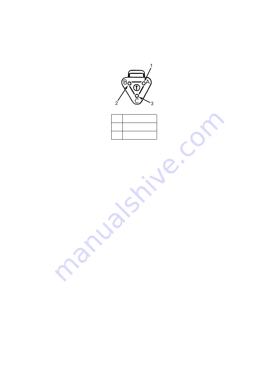
1.
Red (8D)
2.
White (8DP)
3.
Black (CH)
Fuel Solenoid Connector Pin Identification
AEA633
Содержание T-1000R
Страница 14: ...Safety Precautions 2 6 Warning Decals 2e24151g0 ...
Страница 18: ...Specifications 3 4 ENGINE CLUTCH Engagement 600 100 RPM Dynamic Torque 66 fT lb 89 5 N m minimum 1600 RPM ...
Страница 34: ...Maintenance Inspection Schedule 4 10 ...
Страница 57: ...Unit Description 5 23 Purge Mode UT Series 1 3 4 5 2 ...
Страница 67: ...Unit Description 5 33 Zone 1 Cool and Zone 2 Cool UT SPECTRUM Units ...
Страница 69: ...Unit Description 5 35 Purge Mode UT SPECTRUM Units ...
Страница 71: ...Unit Description 5 37 Zone 1 Cool and Zone 2 Heat UT SPECTRUM Units ...
Страница 72: ...Unit Description 5 38 ...
Страница 74: ...Diesel Electric Menu 6 28 Adjust Brightness 6 29 Time 6 30 ...
Страница 120: ...Operating Instructions Standard HMI 7 18 ...
Страница 152: ...Engine Maintenance 9 14 T Series Fuel and Oil System Components TK 376 ...
Страница 154: ...Engine Maintenance 9 16 T Series Fuel and Oil System Components TK 270 ...
Страница 156: ...Engine Maintenance 9 18 UT Series Fuel System Components AMA768 ...
Страница 172: ...Engine Maintenance 9 34 T Series Engine Mounting Components for 2 Cylinder Engine ...
Страница 184: ...Engine Maintenance 9 46 ...
Страница 238: ...Refrigeration Maintenance 10 54 ...
Страница 246: ...Clutch Maintenance 11 8 ...
Страница 258: ...Structural Maintenance 12 12 ...
Страница 264: ...Mechanical Diagnosis 13 6 ...
Страница 265: ...14 Electric Standby Diagnosis ...
Страница 268: ...Electric Standby Diagnosis 14 4 ...
Страница 269: ...15 Refrigeration System Diagnosis ...
Страница 272: ...Refrigeration System Diagnosis 15 4 ...
Страница 280: ...Remote Evaporators 16 8 ...
Страница 282: ...Wiring Diagrams and Wiring Schematics 17 2 ...


