To this chapter contents
6. CYLINDER HEAD/VALVE
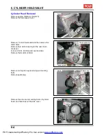
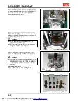
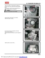
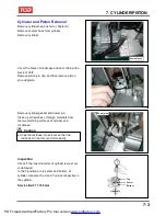
Remove the 2 cylinder head mounting bolts from
cylinder head right side, and then remove 4 nuts
and washers from cylinder head upper side.
Remove the cylinder head.
4 Nuts
2 bolts
Remove cylinder head gasket and 2 dowel pins.
Remove chain guide.
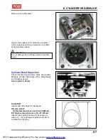
Clean up residues from the matching surfaces of
cylinder and cylinder head.
Caution
●
Do not damage the matching surfaces of
cylinder and cylinder head.
●
Avoid residues of gasket or foreign materials
falling into crankcase as cleaning.
Gasket
Chain guide
Dowel pins
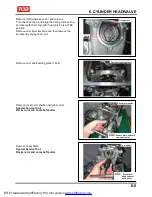
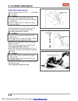
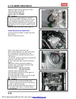
Use a valve cotter remove & assembly tool to
press the valve spring, and then remove valves.
Caution
●
In order to avoid loosing spring elasticity, do not
press the spring too much. Thus, press length
is based on the valve cotter in which can be
removed.
Special Service Tool:
Valve cotter remove & assembly tool
Valve cotter
remove and
assembly tool
Inlet valve
Inner spring
Spring retainer
Exhaust valve
Outer spring
Cotter
6-6
PDF created with pdfFactory Pro trial version
www.pdffactory.com
Содержание BLADE 250
Страница 1: ...BLADE 250 300 SERVICE MANUAL PDF created with pdfFactory Pro trial version www pdffactory com ...
Страница 145: ...13 BODY COVER Mechanism Diagram 13 1 13 PDF created with pdfFactory Pro trial version www pdffactory com ...
Страница 217: ...Home page Contents 18 ELECTRICAL DIAGRAM 18 18 1 PDF created with pdfFactory Pro trial version www pdffactory com ...
Страница 218: ...Home pae Contents 18 ELECTRICAL DIAGRAM Notes 18 2 PDF created with pdfFactory Pro trial version www pdffactory com ...

