To this chapter contents
6. CYLINDER HEAD/VALVE
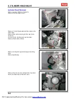
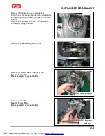
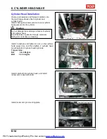
Remove left crankcase cover, and turn the
Turn the drive face, and align the timing mark on the
sprocket with that of cylinder head, piston is at TDC
position.
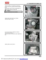
Remove cam sprocket bolts and then remove the
sprocket by prying chain out.
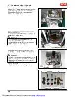
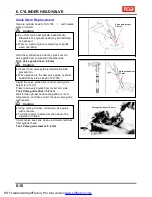
Remove cam shaft setting plate (1 bolt).
Remove rocker arm shafts and rocker arms.
Special Service Tool:
Rocker arm and cam shaft puller
2 bolts
Timing mark
Cam shaft setting plate
Rocker arm shafts
Rocker arm shaft and
cam shaft puller
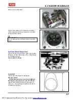
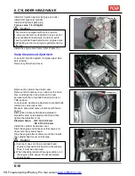
Remove cam shafts.
Special Service Tool:
Rocker arm and cam shaft puller
Cam shafts
Rocker arm
shaft and cam
shaft puller
6-5
PDF created with pdfFactory Pro trial version
www.pdffactory.com
Содержание BLADE 250
Страница 1: ...BLADE 250 300 SERVICE MANUAL PDF created with pdfFactory Pro trial version www pdffactory com ...
Страница 145: ...13 BODY COVER Mechanism Diagram 13 1 13 PDF created with pdfFactory Pro trial version www pdffactory com ...
Страница 217: ...Home page Contents 18 ELECTRICAL DIAGRAM 18 18 1 PDF created with pdfFactory Pro trial version www pdffactory com ...
Страница 218: ...Home pae Contents 18 ELECTRICAL DIAGRAM Notes 18 2 PDF created with pdfFactory Pro trial version www pdffactory com ...

