


To this chapter contents
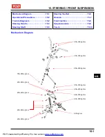
15. STEERING / FRONT SUSPENSION
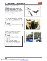
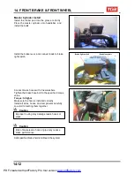
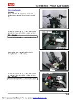
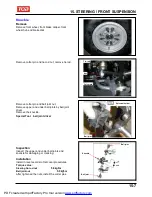
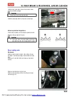
Loosen 2 screws, and then remove handle left
switch and choke hosing.
2 screws
Remove switch wire band.
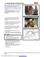
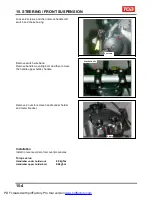
Remove handle mounting bolt, and then remove
the handle upper holder, handle.
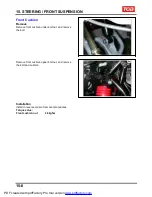
Remove 2 nuts to remove handle under holder
and meter bracket.
4 socket bolts
2 Nuts
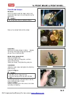
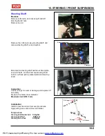
Installation
Install in reverse order of removal procedures.
Torque value:
Handlebar under holder nut
4.0kgf-m
Handlebar upper holder bolt
2.4kgf-m
15-4
PDF created with pdfFactory Pro trial version
www.pdffactory.com
Содержание BLADE 250
Страница 1: ...BLADE 250 300 SERVICE MANUAL PDF created with pdfFactory Pro trial version www pdffactory com ...
Страница 145: ...13 BODY COVER Mechanism Diagram 13 1 13 PDF created with pdfFactory Pro trial version www pdffactory com ...
Страница 217: ...Home page Contents 18 ELECTRICAL DIAGRAM 18 18 1 PDF created with pdfFactory Pro trial version www pdffactory com ...
Страница 218: ...Home pae Contents 18 ELECTRICAL DIAGRAM Notes 18 2 PDF created with pdfFactory Pro trial version www pdffactory com ...