


To this chapter contents
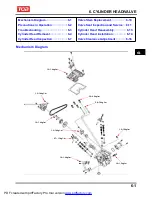
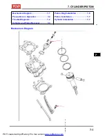
6. CYLINDER HEAD/VALVE
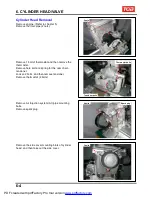
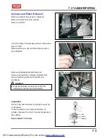
Cylinder Head Removal
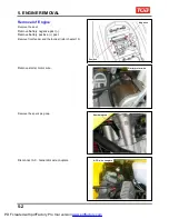
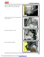
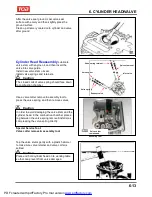
Remove engine. (Refer to chapter 5)
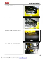
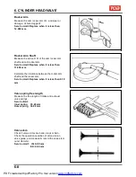
Remove the inlet pipe (2 nuts).
Remove 1 bolt of thermostat and then remove the
thermostat.
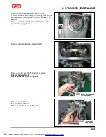
Remove hole bolt and spring for the cam chain
tensioner.
Loosen 2 bolts, and then remove tensioner.
Remove thermostat (2 bolts).
2 nuts
Thermostat bolts
Tensioner bolts
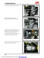
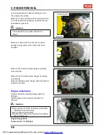
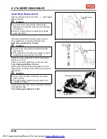
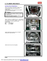
Remove Air Injection system (AI) pipe mounting
bolts.
Remove spark plug.
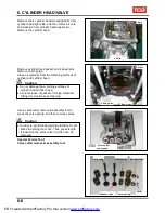
Remove the side cover mounting blots of cylinder
head, and then take out the side cover.
4 bolts
3 bolts
Spark plug
6-4
PDF created with pdfFactory Pro trial version
www.pdffactory.com
Содержание BLADE 250
Страница 1: ...BLADE 250 300 SERVICE MANUAL PDF created with pdfFactory Pro trial version www pdffactory com ...
Страница 145: ...13 BODY COVER Mechanism Diagram 13 1 13 PDF created with pdfFactory Pro trial version www pdffactory com ...
Страница 217: ...Home page Contents 18 ELECTRICAL DIAGRAM 18 18 1 PDF created with pdfFactory Pro trial version www pdffactory com ...
Страница 218: ...Home pae Contents 18 ELECTRICAL DIAGRAM Notes 18 2 PDF created with pdfFactory Pro trial version www pdffactory com ...