background image


115 


4-2. Parallel Operation 

The LSG Series can be connected in parallel to increase the total 
power capacity of a single unit. The LSG Series can operate with up 
to 5 units in parallel. A single unit is designated as a master unit and 
any other connected units as slaves.  
Only units of the same type and rating can be used in parallel or 
alternatively, the LSG-2100S booster pack can be used as a slave 
with the LSG-1050.  
When a master unit is used in parallel mode, to ensure stability, the 
response speed will drop down to 1/2 if it was originally 1/1. You can 
however, reset the response speed back (or to another value) in the 
Main>Configure menu.


Parallel Operation by boosters

 do not support Current Low Range. 


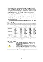
4-2-1.  Capacity 

Model 

Single Unit  2 Units 

3 Units 

4 Units 

5 Units 

LSG-175 

150V 
35A  
175W 

150V 
70A 
350W 

150V 
105A 
525W 

150V 
140A 
700W 

150V 
175A 
875W 

LSG-350 

150V 
70A 
350W 

150V 
140A 
700W 

150V 
210A 
1050W 

150V 
280A 
1400W 

150V 
350A 
1750W 

LSG-1050 

150V 
210A 
1050W 

150V 
420A 
2100W 

150V 
630A 
3150W 

150V 
1680A 
4200W 

150V 
1050A 
5250W 

LSG-1050 
+LSG-2100S 
Boosters* 

150V 
630A 
3150W 

150V 
1050A 
5250W 

150V 
1470A 
7350W 

150V 
1890A 
9450W 

N/A 

* The LSG-2100S booster packs do not have a control panel. They can only be 
used as slaves with a single LSG-1050 in parallel.    


4-2-2.  Connection  

Description 

The J1 and J2 connectors are used for control 
during parallel operation. Up to 5 units can be 
used in parallel.  

Note 

Only the rear panel terminals can be used for 
parallel operation, the front panel terminals have a 
lower current rating and thus should not be used 
for parallel operation. 

Содержание LSG SERIES

Страница 1: ...LSG SERIES INSTRUCTION MANUAL ELECTRONIC LOAD LSG SERIES LSG 175 LSG 350 LSG 1050 LSG 2100S B71 0408 01 ...

Страница 2: ...out this instruction manual When copying the part or all of contents of this instruction manual seek the copyright holder In addition the specifications of the product and the contents of this instruction manual are subject to change without notice for improvement Please check to our website for the latest version About Version of LSG Series This manual will correspond to the Ver 1 27 the firmware...

Страница 3: ...t Settings 12 1 4 4 Setting the Date and Time 13 1 4 5 Load Wiring 14 1 4 6 Load Wire Connections 16 1 4 7 Using the Front Panel Input Terminals 17 1 4 8 Using the Rear Panel Input Terminals 18 1 4 9 Using the Terminal Cover PEL 011 18 1 4 10 Using the Terminal Cover PEL 013 20 1 4 11 Remote Sense 21 1 4 12 Firmware Update 22 1 4 13 Conventions 23 1 4 14 Help Menu 27 2 OPERATION 28 2 1 Basic Opera...

Страница 4: ...evel 43 2 3 2 2 Von Voltage Latch 43 2 3 2 3 Von Voltage Delay 44 2 3 3 Timer Functions 44 2 3 3 1 Count Time 44 2 3 3 2 Cut Off Time 45 2 3 4 Auto Load Configuration 45 2 3 5 Load Off Mode and Load Off Range 46 2 4 Step Resolution Configuration 46 2 4 1 Cursor Mode Configuration 46 2 4 2 Step Mode Configuration 47 2 5 Protection Settings 48 2 5 1 OCP 48 2 5 2 OPP 49 2 5 3 UVP 50 2 5 4 UVP Ring Ti...

Страница 5: ...Settings 65 2 8 10 2 User s Default Setting 65 3 Function MENU 66 3 1 Function Menu Overview 66 3 1 1 Select a Function 66 3 1 2 Turning on the Load with the Selected Function 67 3 1 3 Complete Ring Time 67 3 1 4 NSEQ Timer 68 3 2 Program 69 3 2 1 Program Overview 69 3 2 2 Create a Program 70 3 2 3 Create a Program Chain 73 3 2 4 Running a Program or Chain 74 3 3 Sequence 75 3 3 1 Normal Sequence ...

Страница 6: ...14 1 Trigger Signal Output 113 4 1 14 2 Current Monitor Output 114 4 2 Parallel Operation 115 4 2 1 Capacity 115 4 2 2 Connection 115 4 2 3 Configuration 116 4 2 4 Turning the Load On 118 4 2 5 Disable Parallel Mode 118 5 REMOTE CONTROL 119 5 1 Interface Configuration 119 5 1 1 Configure to USB Remote Interface 119 5 1 2 Configure GP IB Interface 119 5 1 3 Configure RS 232C 120 5 1 4 RS 232C USB R...

Страница 7: ...7 7 6 CP Mode 143 7 7 7 Slew Rate 143 7 7 8 Meter 144 7 7 9 Dynamic Mode 145 7 7 10 Soft Start 147 7 7 11 Remote Sensing 147 7 7 12 Protection Function 147 7 7 13 Sequence 148 7 7 14 Other 149 7 7 15 Analog External Control 149 7 7 16 Front Panel BNC Connector 150 7 7 17 General 151 7 8 LSG Series Dimensions 152 7 8 1 LSG 175 LSG 350 152 7 8 2 LSG 1050 153 7 8 3 LSG 2100S 153 ...

Страница 8: ......

Страница 9: ...aution items required to safely use the product The following pictorial indication and warning character indication are provided Pictorial indication Some part of this product or the instruction manual may show This pictorial indication In this case if the product is incorrectly used in that part a serious danger may be brought about on the user s body or the product To use the part with this pict...

Страница 10: ...an input protection fuse is blown the product does not operate When the fuse is blown the user can replace it However replace it correctly observing the warning and caution items that are provided in the section of the instruction manual where the fuse replacement is explained If the fuse is incorrectly replaced a fire may occur Changing the power supply voltage The rated power supply voltage cann...

Страница 11: ...flammable or explosive gas or steam is generated or stored may result in an explosion and fire Do not operate the product in such an environment Also use in and around a place where a corrosive gas is generated or spreading causes a serious damage to the product Do not use the product in such an environment Do not let foreign matter in Do not insert metal and flammable materials into the product f...

Страница 12: ...ith its performance and specifications stable For consultation about the product calibration call the dealer or the company or each sales office where you bought the product Daily maintenance When you clean off the dirt of the product covers panels and knobs avoid solvents such as thinner and benzene Otherwise paint may peel off or the resin surface may be affected To wipe off the covers panels an...

Страница 13: ...is extremely robust and capable of molding to any test environment Please note that throughout this manual the term LSG Series refers to any one of the models in the series lineup unless specifically stated otherwise 1 1 1 Model Line Up There are a total of 3 DC electronic load models and 1 booster pack model Model Operating Voltage DC Current Power LSG 175 1 5V 150V 35A 175W LSG 350 1 5V 150V 70A...

Страница 14: ...tance control Front panel trigger out BNC Front panel current monitoring BNC Analog external control 1 2 Accessories 1 2 1 Accessories Standard Accessories Part number Description Accessories CD ROM Instruction manual Programming manual USB driver Region dependent Power cord PEL 011 Load input terminal Cover x1 M3 Screw x1 PEL 012 Terminal fittings 2 sets of bolts nuts springs washers type M8 M8 x...

Страница 15: ...t for booster LSG 2100S for EIA JIS GRA 414 E Rack mount frame for LSG 175 LSG 350 LSG 1050 EIA GRA 414 J Rack mount frame for LSG 175 LSG 350 LSG 1050 JIS GTL 248 GP IB cable 2 0m GTL 246 USB cable Type A Type B PEL 010 Dust Filter PEL 004 GP IB option 1 2 2 Package Contents Check the contents before using the instrument Opening the box Contents single unit Main unit Accessories CD Terminal fitti...

Страница 16: ...ort Air inlet LCD Display Power key FUNC File Help Utility Short Load On Off USB Port Preset and Shift keys Number pad Clear Lock and Enter keys Main Local Scroll wheel Function keys Input terminals I MON OUT TRIG OUT LSG 1050 P0 P1 P4 P7 CAL P2 P5 P8 Lock P3 P6 P9 Utility Local File 0 1 4 7 2 5 8 3 6 9 Enter Clear Shift Preset Load On Off Main Help FUNC Short TRIG OUT I MON OUT 1 5 150V 1050W 0 7...

Страница 17: ...program function sequence function or other special functions File FUNC Shift File Shift FUNC Accesses the file system Help Utility Help Help Access the help menu Utility Help Shift Utility Shift Help Access the utility menu Short Short Pressing the Short key will simulate shorting the input terminals The Short key will be lit when active Load on off Load On Off Turns the load on or off The Load O...

Страница 18: ...ative terminal Positive terminal IMON Out I MON OUT Current monitor BNC terminal Output connector used to monitor the current by outputting a voltage An output voltage of 1V corresponds to the full scale current for the H and L ranges 0 1V corresponds to the full scale current in the M range TRIG OUT TRIG OUT Trigger out BNC terminal Outputs a pulse signal during sequence or dynamic operation The ...

Страница 19: ... GROUNDING CONDUCTOR MUST BE REFER SERVICING TO QUALIFIED PERSONNEL CONNECTED TO GROUND Remote sense inputs Frame control ports J1 J2 RS 232C port USB port USB device port Exhaust fan GP IB Power socket and switch Rear panel inputs port LSG 1050 P0 P1 P4 P7 CAL P2 P5 P8 Lock P3 P6 P9 Utility Local File 0 1 4 7 2 5 8 3 6 9 Enter Clear Shift Preset Load On Off Main Help FUNC Short TRIG OUT I MON OUT...

Страница 20: ... used for parallel operation control Exhaust fan The exhaust fan is used to expel the heat from the unit Please ensure there is at least 20cm distance between any object and the fan Rear Panel Input terminals Rear Panel Input Terminals Electrically connected to the front panel input terminals Accepts M8 bolts or M4 M3 sized screws See page 18 for connection details Remote Sensing Terminals Sensing...

Страница 21: ...panel Softkeys Setting area The setting area is used to display and edit the settings for the current mode function Measurement area Displays the voltage current and power values Date Displays the date Mainframe status panel The mainframe status panel displays the status of the load remote control and short function When an icon is green it indicates that the function is off When the icon is orang...

Страница 22: ...ng conventions used throughout the user manual 1 4 1 Rack Mount Kits Description The LSG Series has a number of rack mount options for installation The GRA 413 rack mounts are suitable for the LSG 2100S booster pack The GRA 414 rack mounts are capable of holding 1x LSG 1050 or 2x LSG 175 350 units For installation details please see the GRA 413 and GRA 414 Rack Mount Assembly Manual Please see you...

Страница 23: ...11 GRA 414 E EIA standard 132 382 5 477 6 GRA 414 J JIS standard 149 382 5 477 6 ...

Страница 24: ... ON STBY key again for a second Note If the LSG Series fails to start up properly or does not turn on please see your local distributor 1 4 3 Load Default Settings Description When first using the LSG Series recall the factory default settings to ensure the unit is in a known state See page 127 for a list of the default settings Operation 1 Press Shift File FUNC Select Media Default F1 Select Fact...

Страница 25: ...les when saving files The date and time is shown on top of the display Operation 1 Press Shift Utility Help Time Set F4 to set the date and time Settings Month Day Year Hour Minute System Info Load Interface Time Set LOAD RS232 31 Oct 2013 Other 9 Hour 0 Year 2012 Minute Day Month 9 3 Date Time Date ...

Страница 26: ...000 11 684 0 16072 380 000 10 4038 0 2027 328 00 9 26592 0 25551 283 0 8 25246 0 32242 245 1 7 34822 0 40639 211 2 6 54304 0 51266 181 3 5 82676 0 64616 158 4 5 18922 0 81508 135 5 4 62026 1 02762 118 6 4 1148 1 29593 101 7 3 66522 1 6341 89 8 3 2639 2 0605 73 9 2 90576 2 59809 64 10 2 58826 3 27639 55 11 2 30378 4 1328 47 12 2 05232 5 20864 41 13 1 8288 6 56984 35 14 1 62814 8 282 32 Load Line In...

Страница 27: ...imiting Load line inductance Load line inductance can be reduced in two ways 1 Ensure load wires are as short as possible and twist the positive and negative load wires together 2 Current change can be limited by limiting the slew rate or response speed when switching in CR and CC mode Twisted pair will be shown on any connection diagram where the load wires should be twisted together DUT Electron...

Страница 28: ...tage is not exceeded The maximum input voltage is 150 volts DUT Electronic Load Caution If the polarity to the input terminals is reversed the reverse voltage protection function is tripped The reverse voltage protection function is tripped when reverse voltages greater than 0 3V are detected Warning Do not touch any of the input terminals when the unit is on Warning Connecting the input terminals...

Страница 29: ...y connected to the rear panel terminals Step 1 Turn the power off from the rear panel or put the unit into standby mode 2 Turn the power off from the DUT 3 Connect the load wires to the input terminals Connect the positive input terminal on the load generator to the high potential output of the DUT Connect the negative input terminal to the low potential output of the DUT potential potentional Pos...

Страница 30: ...n the load generator to the high potential output of the DUT Connect the negative input terminal to the low potential output of the DUT potentinal potential 1 4 9 Using the Terminal Cover PEL 011 Description The rear panel terminal cover should be used to prevent electric shock The rear panel terminal covers should always be used when connecting a load to the rear panel terminals As the front pane...

Страница 31: ...over to the bottom cover 1 2 Line up the bottom cover with the notches in the output terminals 3 Place the top terminal cover over the bottom cover 2 Detail 3 4 Use your thumb to slide the terminal covers shut as shown in the diagram below 4 ...

Страница 32: ...specially true when using the load generators in parallel Like the PEL 013 terminal cover the PEL 011 is used to prevent electric shock The rear panel terminal covers should always be used when connecting a load to the rear panel terminals Caution Ensure the power is off before making any connections to the booster pack 1 Wrap the insulation sheets around the terminals and load cables as shown bel...

Страница 33: ...e induced inductance and using the Vsense terminals compensates the voltage drop seen across the load leads especially leads with higher resistance This is useful when used in CV CR or CP mode Steps 1 Turn the power off from the rear panel or put the unit into standby mode 2 Turn the power off from the DUT 3 Connect the sense wires to the sense terminals Connect the positive sense S terminal to th...

Страница 34: ... website address 4 To view other system information press System F1 and select Memo System Info Load Interface Time Set LOAD RS232 31 Oct 2013 Model LSG xxxx http www texio co jp Firmware Ver x xx xxx Serial Number xxxxxxxx Other Update Firmware 1 Insert a USB drive into the USB port Ensure the USB drive has the firmware file located in the root directory 2 Press Shift File FUNC 3 Select USB with ...

Страница 35: ...unction keys Soft menu keys Mode CC I Range H 35A V Range L 15 V Function Static Configure 0 000V 0 000A 0 00w SlewRate 2500 00 CC B Value 0 000 CC A Value 0 000 LOAD RS 232 A Value Fine 31 Oct 2013 mA us A A Select Sub Menu Configure Pressing this type of soft menu key will enter a submenu Toggle Parameter or State Mode CC Function Item Parameter or State This type of soft menu icon has the funct...

Страница 36: ... Fine 03 09 12 mA uS A A LOW Middle High 0 35A 3 5A 35A label Popup window Parameter selection Parameter Input The scroll wheel Enter key and number pad can be used to edit parameter values Number pad Scroll wheel Enter key P0 P1 P4 P7 CAL P2 P5 P8 Lock P3 P6 P9 0 1 4 7 2 5 8 3 6 9 Clear Enter 1 Use the scroll wheel to move the cursor to the desired parameter A scroll bar is shown when there are a...

Страница 37: ... 4 Press the Enter key again to finish editing the parameter value Clearing a Value When editing a parameter with the number pad pressing the Clear key will restore the parameter to the previous value Using the Scroll Wheel to Edit a Parameter To edit a parameter using the scroll wheel simply turn the scroll wheel Clockwise increases the value counterclockwise decrease the value Pressing the scrol...

Страница 38: ...r is highlighted allows you to set the step resolution by a digit value An orange line will appear under the currently selected digit value Repeatedly pressing the scroll wheel moves to the next digit Mode CC I Range H35A V Range L 15V Function Static Configure 0 000V 0 000A 0 00w SlewRate 2500 00 CC B Value CC A Value 0 000 LOAD RS232 A Value Cursor 31 Oct 2013 mA us A A 1 000 Cursor Mode Indicat...

Страница 39: ...ame or memo press Save F3 1 4 14 Help Menu When any function key has been pressed or when a menu has been opened the HELP key can be used to display a detailed description Help Selection 1 Press any function key or soft menu key 2 Press Help to see the help contents on that particular function key or menu 3 Use the scroll to navigate the help contents 4 Press the Exit F5 key to exit the help menu ...

Страница 40: ...tically Operation 1 Make sure the load is off 2 Press Main 3 Select CC mode with the Mode F1 soft key 4 Select the current range with the I Range F2 soft key Range High Middle Low 5 Select the voltage range with the V Range F3 soft key Range High Low 6 Set the current level parameters using the scroll wheel and number pad For Static mode set CC A Value and or CC B Value For Dynamic mode set Level1...

Страница 41: ...g modes 2 1 2 CR Mode Description In Constant Resistance Mode the unit will maintain a constant resistive load by varying the current CR mode uses ohms Ω resistance or siemens S conductance for the setting units For more details on CR mode see the appendix on page 134 Warning If you change the mode or the range when the load is already on the load will be turned off automatically Operation 1 Make ...

Страница 42: ...e L 15V Function Static Configure 0 000V 0 000A 0 00w SlewRate 250 000 CR B Value 0 04082 CR A Value 0 04082 LOAD RS232 A Value Fine 31 Oct 2013 mA uS Ω Ω Mode Current range Voltage range Active setting Conductance Resistances Conductance Resistance settings Note Basic CR mode configuration is complete See page 37 for more configuration options The current range and voltage range applies to all th...

Страница 43: ...V Range F3 soft key Range High Low 6 Set the voltage level parameters using the scroll wheel and number pad Set CV A Value and or CV B Value The maximum and minimum voltage levels depend on the selected voltage range 7 Set the remaining basic configuration settings such as the response settings See page 37 for details Display Mode CV I Range H 35A V Range L 15V Response Slow Configure 0 000V 0 000...

Страница 44: ...ge F2 soft key Range High Middle Low 5 Select the voltage range with the V Range F3 soft key Range High Low 6 Set the power level parameters using the scroll wheel and number pad For Static mode set CP A Value and or CP B Value For Dynamic mode set Level1 and Level2 The maximum and minimum power levels depend on the selected current range For static mode the parameter that is set last becomes the ...

Страница 45: ...rent range and voltage range applies to all the operating modes 2 1 6 CV Mode Description CV mode can be added to CC CR and CP mode The CV settings apply to all applicable modes Operation 1 Make sure the load is off 2 Press Main to return to the main menu for the current mode 3 Set the CV voltage level You may need to scroll down to the CV setting Range OFF rated voltage 5 Display Mode CP I Range ...

Страница 46: ...d can be turned on via remote control See the programming manual The load can be turned on via external control See page 109 Display Mode CP IRange H 35A VRange L 15V Function Dynamic Configure 1 500V 0 000A 1 50w Timer1 0 025 Level2 0 00 Level1 0 00 LOAD RS232 Fine 31 Oct 2013 mS W W LOAD on 2 1 8 Shorting the Load Description The Short key can be used to simulate a short circuit of the load inpu...

Страница 47: ... same time Pressing the Short key again will also turn the load off again as well If the load is already on and the Short key is pressed then when the Short key is pressed again the load will remain on the electronic load will return to its previous load condition 2 1 9 Safety Short Description When activated the safety short function only allows the short key to be used when the load is already o...

Страница 48: ...Other F2 and set the Short Function When set to OFF the Short key is disabled and all short configuration options in the Main Configure Other menu are also disabled When set to ON the Short key is enabled Short Function OFF ON 2 1 12 Locking the Front Panel Controls Description The keys and scroll wheel on the front panel can be locked to prevent settings from being changed Operation 1 The keys ca...

Страница 49: ... Static mode can only switch between the two levels manually while Dynamic mode switches between each level automatically based on a timer Static mode A Value B Value Dynamic mode Level1 Level2 When the unit is set to static mode only one value A Value or B Value can be active at a time The active value is shown in the Operation Status Panel Function Static Configure 0 00w LOAD RS232 SHORT A Value...

Страница 50: ...ttings into consideration when setting the timers The frequency of the dynamic switching is output via the TRIG OUT BNC To select whether A Value or B Value is the active setting press the Shift Preset keys The active value will be shown in the Operation Status Panel The load can be on when switching between A Value and B Value Display Static Mode Mode CP I Range H 35A V Range H 150V Function Stat...

Страница 51: ...set to either discrete values or as a percentage of a set value The setting applies to all applicable operation modes By default the units are set to Value When Percent is chosen 100 100 of the Set power current or resistance value Operation 1 Make sure the load is off 2 Press Main Configure F5 Other F2 and set the Dyna Level setting Range Value Percent Display Percent Setting Mode CP I Range H 35...

Страница 52: ...er F2 and set the Dyna Time setting Range T1 T2 Freq Duty 2 2 4 Slew Rate Description The current slew rate can be set for CC and CR mode The slew rate setting is used to limit the change in current when switching For static mode only a single slew rate can be set Operation 1 Make sure the load is off 2 Press Main 3 Set the slew rate s using the scroll wheel and number pad For static mode only a s...

Страница 53: ... when used in CV mode Response speed settings are only applicable to CV mode A response speed that is too fast could cause the unit to be unstable Reducing the response speed can improve stability Operation 1 Make sure the load is off 2 Press Main Make sure the unit is in CV mode by using the Mode F1 soft key 3 Select the response speed with the Response F4 soft key Range Slow Fast Display Mode CV...

Страница 54: ...1 2 1 5 1 10 2 3 Advanced Configuration Settings Use the advanced configuration settings to configure settings other than those described in the basic configuration chapter 2 3 1 Soft Start Setting Description The soft start setting is used to limit the amount of input current at start up or from when the Von Voltage threshold is tripped The soft start setting only applies to CC CR mode Input I Ti...

Страница 55: ...the Von Voltage level Range Von Voltage 0 00 rating voltage 2 3 2 2 Von Voltage Latch Description When Von Latch is set to ON the load will continue to sink current after being latched even if the voltage drops below the Von Voltage threshold level When Von Latch is set to OFF the load will turn off when the voltage drops below the Von Voltage threshold level By default Von Latch is set to OFF Tim...

Страница 56: ...figure F5 Other F2 and set the Von Delay time Range Von Delay OFF 0 5 60ms CR mode can have the delay time set separately from the other modes called Von Delay CR when in CR mode 2 3 3 Timer Functions 2 3 3 1 Count Time Description When Count Time is set to on it will count the elapsed time from when the load was turned on to when it was turned off This function is applicable to manual and automat...

Страница 57: ...ge H 35A V Range L 15V Function Dynamic Configure 0 000V 0 000A 0 00w Timer1 0 025 Level2 0 00 Level1 0 00 LOAD RS232 Fine 31 Oct 2013 mS W W 0 00 05 Cut off time Time Up Voltage 5 1223V Enter Voltage at cut off time 2 3 4 Auto Load Configuration Description The LSG Series can be configured to automatically load the last program normal sequence fast sequence or load setting at startup By default t...

Страница 58: ... OFF ON 3 Select Load Off Range setting When set to OFF the load will stay on when the range is changed Load Off Range OFF ON 2 4 Step Resolution Configuration There are two different ways to set the set resolution when using the scroll wheel to edit parameters Step Mode and Cursor Mode Step Mode is the default method Only one mode can be active at a time When one mode is active the other mode is ...

Страница 59: ...tting is configured separately for each current range Settings Description CCH Step CC mode IRange High CCM Step CC mode IRange Middle CCL Step CC mode IRange Low CRH Step CR mode IRange High CRM Step CR mode IRange Middle CRL Step CR mode IRange Low CVH Step CV mode VRange High CVL Step CV mode VRange Low CPH Step CP mode IRange High CPM Step CP mode IRange Middle CPL Step CP mode IRange Low Oper...

Страница 60: ...lector output by a photocoupler The protection settings can be used regardless of whether the remote sense connections are used or not 2 5 1 OCP Description For OCP the LSG Series can be configured to either limit the current or turn off the load The OCP levels can be set to 10 higher than the rating current Operation 1 Press Main Configure F5 Protection F1 and set the OCP Level and OCP Setting Ra...

Страница 61: ...rotection F1 and set the OPP Level and OPP Setting Range OPP Level Rating power 10 OPP Setting LIMIT Load Off Alarm When OPP Setting is configured to Load Off a message will be displayed on the screen when OPP is tripped The Enter key must be pressed to clear the alarm message When configured to LIMIT OPP will be displayed on the screen when the OPP is tripped and the power will be limited to the ...

Страница 62: ...AD RS232 A Value Fine 03 09 12 V V UVP Alarm Please Press Enter To Clear Alarm UVP UVP indicator Alarm message when UVP is tripped Mode CV I Range L 0 7A V Range L 15V Response Fast Configure 2 5 4 UVP Ring Time Description The UVP Ring Time settings allows the UVP alarm to keep sounding for a user set amount of time after the UVP has been tripped Operation 1 Press Main Configure F5 Protection F1 ...

Страница 63: ...P Alarm Please Press Enter To Clear Alarm OVP OVP indicator Alarm message when OVP is tripped Mode CV I Range L 0 7A V Range L 15V Response Fast Configure 2 5 6 UnReg Description The UnReg error message will appear on the display when the electronic load is operating in an unregulated state Alarm The UnReg indicator will appear on the display when the set load is inadequate for the source To clear...

Страница 64: ... Fine 03 Sep 2012 V V Para Para indicator Mode CV I Range L 0 7A V Range L 15V Response Fast Configure 2 5 8 RVP Description If the RVP is tripped the LSG Series will turn off the load Alarm The RVP error message indicates when the terminal voltage is negative The Enter key must be pressed to clear the alarm message Display 2 596V 500 06mA 1 2982w CV B Value 15 000 CV A Value 15 000 LOAD RS232 A V...

Страница 65: ... interface such as key press tones and scrolling tones Operation 1 Press Shift Utility Help Other F5 2 Set the Speaker settings on or off When set to OFF the speaker setting will not disable the tones for Go NoGo or protection alarms 2 6 1 2 Alarm Tone Settings Description The alarm tone for the unit during normal operation and for Go NoGo testing can be turned on or off in the utility menu Operat...

Страница 66: ...he set values current voltage etc in realtime The Old setting is will only update the values after the Enter key is pressed Operation 1 Press Shift Utility Help Other F5 2 Set the Knob type and Slave knob settings Range Knob type Updated Old 2 6 4 Language Settings Description The LSG Series supports only English Operation 1 Press Shift Utility Help Other F5 2 Set the Language setting Supported la...

Страница 67: ...t from a center value Operation 1 Press Main Configure F5 Go NoGo F3 2 Select Entry Mode and choose how to set the pass fail limits Value will allow you to set the limits as discrete values Percent will allow you to set the limits as a percentage offset from a center value 3 If Entry Mode was set to Value Set the High Low limit values High Low 0 rating current voltage 0 rating current voltage 4 If...

Страница 68: ...is ON SPEC will appear in the Operation Status Panel This means the unit is ready for Go NoGo testing 3 Turn the load on The test starts from the time the load was turned on the Delay Time Display GO Mode CP IRange H 35A VRange L 15V Function Dynamic Configure 0 000V 0 000A 0 00w Timer1 0 025 Level2 0 00 Level1 0 00 LOAD RS232 Fine 31 Oct 2013 mS W W SPEC test ON SPEC GO Test result Display NG Mod...

Страница 69: ...lowing order Active settings Internal memory USB This can be best described in the picture below Local Memory Media Memory Media USB Memory data Setup data x1 Nseq data x1 Fseq data x1 Preset data x1 Memory data M001 M256 Setup data 001 100 Preset data P0 P9 Memory data M001 M256 Setup data 001 100 Nseq data x1 Fseq data x1 Preset data P0 P9 Active Settings Memory data x1 For example To load Prese...

Страница 70: ...e no S example 3021_00 S Preset Data Preset Data contains the same settings as the Memory Data Preset Data contains the operating mode range response and Go NoGo settings Internal Format P0 P9 External Format model no_file no P example 3021_00 P NSeq Data NSeq Data contains the Normal Sequence settings Internal Format None External Format model no_file no N example 3021_00 N FSeq Data FSeq Data co...

Страница 71: ...e type of file to save Data Type Memory Data Setup Data Preset Data 4 Select which internal memory location to save the file Memory Setup Memory Preset M001 M256 1 100 P0 P9 5 Press Save F3 to save Save Ok will be displayed when the save has been completed Note Normal Sequence and Fast Sequence data cannot be recalled from or saved to an internal memory slot 2 8 4 Saving Files to USB Memory Descri...

Страница 72: ...C 3 Select USB with the Media F1 soft key 4 Select the Data Type and choose the type of file to save Data Type Memory Data Setup Data Preset Data NSeq FSeq 5 Select Save File and choose a save filename Turn the scroll wheel to increase decrease the file number Memory Setup Memory Preset NSeq FSeq Model_file number M Model_file number S Model_file number P Model_file number N Model_file number F 6 ...

Страница 73: ...p Data has 100 memory slots and Preset Data has 10 memory slots Memory Data Example Active setting M001 M256 MXXX Media Memory Display Save Data Type Memory RS232 31 Oct 2013 Memory M256 A Value Fine CC 0 35A 15V Static LOAD Media Memory Recall Memory Save file location Save file type Operation 1 Press Shift File FUNC 2 Select Memory with the Media F1 soft key 3 Select the Data Type and choose the...

Страница 74: ... USB drive will overwrite all the existing memory slots for the selected data type For Normal or Fast Sequence files the recalled file becomes the active setting as these types of files don t have an internal memory slot Caution You can only recall files from the same model Memory Data Example Media USB Media Memory Recall file M001 M256 MXXX For example if the file 3021_01 M is recalled all the M...

Страница 75: ...e the USB path Rename files or create directories Caution If Machine Type Error is displayed it indicates that the file that you are trying to recall originated from a different model You can only recall files from the same model 2 8 7 Recall Memory Safety Setting Description By default when you try to recall a file or setting from memory a message will appear asking you to press the Enter key to ...

Страница 76: ...to move the cursor to the file folder you wish to rename 2 Press Rename F3 Use the on screen display to enter the ilename A maximum of 8 characters Delete File or Folder 1 Use the scroll wheel to move the cursor to the file folder you wish to delete 2 Press Delete F4 3 Press Delete F4 again to confirm the deletion 2 8 9 Preset The Preset key is used to save and recall preset settings from the fron...

Страница 77: ...fault settings Operation 1 Press Shift File FUNC 2 Select Default with the Media F1 soft key 3 Press Factory Default F2 4 Press Factory Default F2 again to confirm 2 8 10 2 User s Default Setting Description The currently active settings can be set as the User s Default settings Save User s Default Setting 1 Press Shift File FUNC 2 Select Default with the Media F1 soft key 3 Press Save F3 The User...

Страница 78: ...r off Before one of these functions are turned on they should be configured beforehand Sequences or the OCP function respectively Function Select Screen Program Fast Sequence PROG RS232 31 Oct 2013 Normal Sequence OCP Function Select FUNCTION Complete Ring Time NSEQ Timer Elapsed 5 s PROG Operation 1 Press File FUNC 2 Select Function Select and choose a function to turn on or choose to turn off th...

Страница 79: ...on by pressing Shift Load The Load key will turn orange when the load is on The load can be turned off again by pressing the Load key 3 1 3 Complete Ring Time Description The Complete Ring Time function turns the alarm on for a user set amount of time after a program sequence or OCP function has finished Function Select Screen Program Fast Sequence PROG RS232 31 Oct 2013 Normal Sequence OCP Functi...

Страница 80: ...gram Fast Sequence PROG RS232 31 Oct 2013 Normal Sequence OCP Function Select FUNCTION Complete Ring Time NSEQ Timer Elapsed 5 s PROG Operation 1 Press File FUNC 2 Select NSEQ Timer and select whether the current step and total test time is displayed as elapsed time or remaining time Range Elapsed Remaining Default Elapsed Display example Continue NSEQ RS232 31 Oct 2013 Run N Seq 0 000V 0 000A 0 0...

Страница 81: ... different load operations consecutively Each of the different load operations are steps in the program A program starts at step 01 and ends at step 16 A program recalls the operating mode range static dynamic mode response speed and other settings of each step from stored memory It also recalls the Go NoGo settings The same memory settings can be used for multiple steps The execution time of each...

Страница 82: ... the off time between steps P F Time Sets the testing pass fail delay time for GoNo Go testing Short Time Sets the shorting time for the step if any Timing Diagram for Single Step Below is a timing diagram of a single step in a program On Time Off Time Step test time Start of Step End of Step P F End Test Time fixed P F Time 0 04s 0 06s Short Time P F Start Test Time fixed 3 2 2 Create a Program N...

Страница 83: ...P 01 16 4 Select Memory and select which memory location to load for the selected step Settings loaded from the memory location will be used for the selected step The same memory location can be used for multiple steps Memory M001 M256 5 Set the Run setting for the step By default RUN is set to Skip The Auto setting will automatically start and go onto the next step The Manual setting will wait fo...

Страница 84: ...me Off 0 0 119 9 seconds 9 Set the Short Time in seconds Has the same action as pressing the short key See page 36 for details about shorting the load Short Time Off 0 1 seconds On Time 10 Repeat steps 3 to 9 for all the steps in the program A maximum of 16 steps per program can be created Steps that are not configured are set to Skip by default 11 Press Save F3 to save the program and all the ste...

Страница 85: ... they were not created in the current session 2 If Start is not already selected press Select Start F1 and select which program will be used to start the program chain Start P01 P16 3 Select P01 and choose which program will be linked to P01 Selecting OFF will end the chain after P01 Selecting P01 will create an infinite chain Chains need not be linked in sequential order P01 OFF P01 P16 4 Repeat ...

Страница 86: ...s running the screen displays which program step and memory is currently active Press Pause F1 to suspend a test press Continue F1 to resume Press Next F2 to run the next step if its Run setting was set to Manual 5 When a program chain has finished running a list of the Go NoGo results for each step are displayed Press Exit F5 to exit Display Program Chain Running Pause PROG RS232 03 09 12 Step Me...

Страница 87: ... sequences can define the execution time and slew rate of each step On the other hand the execution time for each step in a fast sequence is fixed to the rate Time Base setting set by the user 3 3 1 Normal Sequence Overview Description A normal sequence is comprised of a user defined number of steps that when executed in sequence can be used to simulate a DC load Up to 1000 discrete steps can be c...

Страница 88: ...the following timing settings for each sequence Setting Setting Range Description Start S01 S10 Sets which sequence are used to start a chain of Normal Sequences Seq No S01 S10 Sets the current sequence to edit Memo 12 characters A user created note for the currently selected sequence Mode CC CR CV CP Operating mode for the sequence CV mode is supported Range ILVL Low I range low V range IMVL Midd...

Страница 89: ...mber of steps added using the Insert Point F1 functions Value The current voltage power or resistance setting for the selected operating mode Load ON OFF Turns the load on or off for the selected step RAMP ON OFF When turned on the current transition is evenly ramped from the start of the step to the end of the step When turned off the current transition is stepped Time amplitude Step time Ramp On...

Страница 90: ...iming Edit Configuration Edit Timing Display Previous Menu LOAD RS232 03 09 12 Timing Edit for Normal Sequence Loop Range Mode Infinity ILVL CC Chain Last Last Load Off 0 00000 A OFF Seq No S01 N Seq Off Edit Sequence Start sequence Start S01 Memo No Memo Sequence number Sequence settings Operation 1 Press FUNC Normal Sequence F2 Note that N Seq F1 is off by default Select Start and select the num...

Страница 91: ...isplay Previous Menu LOAD RS232 03 09 12 Data Edit for Normal Sequences RAMP LOAD OFF OFF 000 H PAUSE TRIG OUT OFF OFF 001ms 0001 Insert Point Save Step 0001 Time Value 0 00000 A 00 M 00 S Delete Point Active step number Total number of steps Step settings Operation 1 Press FUNC Normal Sequence F2 2 Select Seq No and select the sequence you wish to edit Start S01 S10 3 Press Edit Sequence F2 to en...

Страница 92: ...fter all the steps for the sequence are complete press Save F3 to save the steps Data Edit for Normal Sequence configuration is complete Go to Timing Edit for Normal Sequences to edit the sequence Page 78 Go to Running a Normal Sequence to run the normal sequence Page 80 3 3 4 Running a Normal Sequence Description A load created with the Normal Sequence function is run the same way as a normal loa...

Страница 93: ... 0003 3 3 5 Fast Sequence Overview Description A fast sequence is comprised of a user defined number of steps that can be executed at a high frequency Unlike normal sequences each step in a fast sequence has the same execution time time base This mode is only available for CC and CR mode Up to 1000 discrete steps can be configured using fast sequences Each fast sequence can have a memo note attach...

Страница 94: ...t Sequence contains the following timing settings for each sequence Setting Setting Range Description Memo 12 characters A user created note for the currently selected sequence Mode CC CR Operating mode for the sequence Range ILVL Low I range low V range IMVL Middle I range low V range IHVL High I range low V range ILVH Low I range high V voltage range IMVH Middle I range high V range IHVH High I ...

Страница 95: ...ce setting for the selected operating mode TRIG OUT ON OFF When TRIG OUT is set to ON a trigger signal is output from the TRIG OUT BNC terminal at the start of the step See page 113 for details Time amplitude TRIG OUT ON TRIG OUT Start of step FILL Overview The FILL function is used to evenly step up the current or resistance value settings from a starting step to a finishing step The Fill Functio...

Страница 96: ...sistance value for the ending step Start_Step 0001 1000 Sets the starting step number End_Step 0001 1000 Sets the ending step number 3 3 6 Timing Edit Configuration Edit Timing Display Previous Menu LOAD RS232 31 Oct 2013 Timing Edit for Fast Sequence Loop Range Mode Infinity ILVL CC RPTSTEP Last Last Load 0004 0 00000 A OFF F Seq Off Edit Sequence Memo 001 Sequence settings Time Base 600 00 ms Op...

Страница 97: ... used in the Fast Sequence Page 85 Go to Running a Fast Sequence to run the fast sequence Page 87 3 3 7 Data Edit Configuration Data Edit Display Previous Menu LOAD RS232 03 09 12 Data Edit for Fast Sequences OFF 0005 Insert Point Save Step 0001 TRIG OUT Value 0 00000 Delete Point Active step number Total number of steps Step settings FILL FILL Display Save Previous Menu End_Step 0010 Start_Step 0...

Страница 98: ...eter Steps can only be selected after they have already been added Steps 0001 1000 RPTSTEP 5 The currently selected step can be deleted using the Delete Point F2 function There cannot be less than 3 steps for fast sequences Fill Function Press FILL F4 to use the fill function Set the fill parameters Start_Value End_Value Start_Step End_Step The fill function can be used any number of times Save Af...

Страница 99: ...e will be shown on the display at the end of the sequence Display Fast Sequence Running FSEQ RS232 31 Oct 2013 Run F Seq 0 998V 153 10mA 0 1528w Step Loop 0001 0023 Current loop number Current step number 3 4 OCP TestAutomation Background The OCP test function creates an automatic test to test the OCP of power supply products This test will test to see when the over current protection of a power s...

Страница 100: ...rent Start C Starting current value for the test End Current End C The current value that will end the test The value must be higher than the OCP value of the DUT you are testing This parameter is used as a fail safe for if the over current protection of the DUT fails If the measured current is reaches End Current value it would then indicate that the power supply OCP failed Step Current Step_C Se...

Страница 101: ...set The voltage trigger level is used to test to see if the voltage output has been reset Note This mode can only be used under CC mode Panel Operation 1 FUNC OCP F4 OCP ON F1 OCP ON Save OCP RS232 31 Oct 2013 Previos Menu OCP No OCP Function Range Low 01 Start C End C Step C 0 00000 0 00001 0 00001 StepT 0 10 Delay Trig V last C 0 00 1 00 0 00001 Select No 2 Select OCP No and select a test setup ...

Страница 102: ...e in steps according to the Step C value until the test has finished The test will start running when the power supply voltage is greater than the Trig V voltage Example OCP Function running OCP RS232 31 Oct 2013 OCP Test 0 998V 153 10mA 0 1528w Set Curr Fetch Volt 2 000 1 500 1 000 0 91 0 92 0 91 Measured voltage for last three steps Measured voltage Current and power Running Set current for the ...

Страница 103: ...The OCP Test will return the current setting of the last step when the power supply s OCP was tripped Power Source OCP timeout OCP RS232 31 Oct 2013 OCP Test 0 998V 0 000mA 0 00w Set Curr Fetch Volt 2 000 1 500 1 000 0 91 0 92 0 91 OCP time out OCP time out indicates that the power supply OCP was not tripped OCP time out will occur if the power supply s OCP fails to trigger This is determined when...

Страница 104: ...am below shows an example of the OPP Test Automation function Example The test watt increases from a starting value Start W to an end value End W The watt increases in steps set by Step_W with a set step time set by Step_T until the power supply s OPP is tripped or the End W watt level is reached Parameters OPP No Selects one of 12 OPP test setup memories Memo A user created note for the currently...

Страница 105: ... to 50s Trig Delay Time Delay Sets a delay corresponding to the time a Trig Voltage can be expected after each step Watt is applied the delay time must be less than the Step time Trig Voltage Trig V Sets the trigger to a level needed to see when the power supply OPP has been triggered When the power supply OPP has been triggered its voltage output will reset The voltage trigger level is used to te...

Страница 106: ...up Start OPP 4 Press OPP F1 to turn the OPP function on if it is off 5 The OPP function can be started by turning the load on by pressing Shift Load On Off The test watt will increase from the Start W value to the End W value in steps according to the Step W value until the test has finished The test will start running when the power supply voltage is greater than the Trig V voltage ...

Страница 107: ...95 Example OPP Function running Results Power Source OPP tripped The OPP Test will return the current setting of the last step when the power supply s OPP was tripped ...

Страница 108: ... Source Config Error Config Error indicates that the power supply voltage is less than the Trig V voltage setting after the test has started This can indicate that the power supply output is not on or that the power supply output or Trig V is incorrectly configured Note In addition to the OPP settings as described above the VON voltage settings must also be set according to the output characterist...

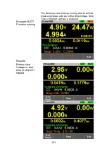
Страница 109: ...rmation about discharge test discharge time battery AH battery WH can be finally seen on the panel The LSG also has a user defined cutoff setting in the event that the Battery test fails The diagram below shows an example of the BATT Test Automation function Example The test will run in the specified mode with defined values and will stop when the defined stop values are reached Vin Current t Slew...

Страница 110: ...tting CP mode t Parameters BATT No Selects one of 12 BATT test setup memories Memo A user created note for the currently selected BATT function Mode Select a discharge operation mode CC CR CP Range ILVL I range low V range low IMVL I range middle V range low IHVL I range high V range low ILVH I range low V range high IMVH I range middle V range high IHVH I range high V range high ...

Страница 111: ...t adjustable for CP mode Stop Volt Sets the voltage at which the test should be interrupted The value must be lower than the battery start voltage Stop Time Sets the time after which the test should be interrupted max value is 999h 59m 59s Stop AH Sets the discharged energy rate at which the test should be interrupted Max value is 9999 99Ah Datalog timer Sets the time interval for data capture Pan...

Страница 112: ...tting SlewRate Stop Time Datalog timer Memo Range SlewRate Stop Volt Stop AH 3 Press the Save F3 to save the selected test setup Start BATT 4 Press BATT F1 to turn the BATT function on if it is off 5 The BATT function can be started by turning the load on by pressing Shift Load On Off ...

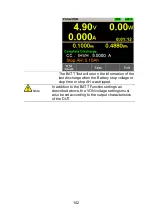
Страница 113: ... test will keep running with its defined mode and values until any of the Stop Voltage Stop Time or Stop AH settings is detected Example BATT Function running Results Battery stop Voltage or stop time or stop AH tripped ...

Страница 114: ... of the last discharge when the Battery stop voltage or stop time or stop AH was tripped Note In addition to the BATT Function settings as described above the VON voltage settings must also be set according to the output characteristics of the DUT ...

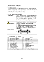
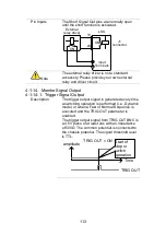
Страница 115: ...See the appendix on page 129 to view the contact pin assignment of the J1 connector WARNING Some pins on the frame control connector have the same potential as the front and rear terminals To prevent electric shock ensure that the cover for both the J1 and J2 External Control connectors are used when the connectors are not in use Pin Assignment FRAME CONT J 1 1 2 19 20 J1 Connector Pin assign No N...

Страница 116: ... EXT V Pin3 EXT V Note The input impedance for external voltage control is 10kΩ Use a stable voltage supply for the external voltage control Caution When using external voltage control make sure no more than 11V is applied across pins 1 and 3 Exceeding this voltage could damage the LSG Series Exceeding 11 8V will cause an EXT OV alarm message to appear which also will reset the voltage output to 0...

Страница 117: ...ce 0V 10V CV Mode Input voltage rated voltage external voltage 10 Input Voltage External Voltage Rated Voltage 0V 10V CP Mode Input power rated power external voltage 10 Input Power External Voltage Rated Power 0V 10V Operation 1 Turn the power off from the LSG Series and from the load 2 Connect the external voltage across pins 1 and 3 of the J1 connector 3 Turn the power on the LSG Series 4 Set t...

Страница 118: ...e configured to vary in proportion to the external resistance or the inverse See page 107 for more details on proportional and inverse resistance control Connection When connecting the external resistance source to the J1 connector use a ferrite core and use twisted pair wiring LSG EXT R J1 connector 3 1 Input Terminals Ferrite Core and twisted wiring Pin1 EXT R Pin3 EXT R Note Use resistors with ...

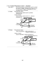
Страница 119: ...ent rated current external resistance 10 Inverse Control Input current rated current 1 external resistance 10 Input Current External Resistance Rated Current 0Ω 10kΩ Proportional control Inverse control CR Mode Proportional Control Input conductance rated conductance external resistance 10 Inverse Control Input conductance rated conductance 1 external resistance 10 Input Conductance External Resis...

Страница 120: ... control Inverse control Note The inverse configuration is recommended for safety reasons In the event that any of the cables become accidentaly disconnected the current voltage power input will drop to the minimum Under similar circumstances using proportional control an unexpectedly high input would result Operation 1 Turn the power off from the LSG Series and from the load 2 Connect the externa...

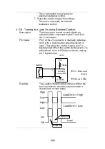
Страница 121: ...puts Pin 7 of the J1 connector is internally pulled up to 5V with a 10kΩ resistor when the switch is open Thus when the switch is open pin 7 is logically high When the switch is closed pin 7 is pulled down to the A COM ground level making pin 7 logically low LSG Switch Analog connector 12 7 5V A COM 10kΩ Pin7 Ext Load On Pin12 A COM Example The LoadOn IN setting determines whether the load is turn...

Страница 122: ...f the J1 connector is used to monitor the load status on or off Pin out The Load On Status pin is a photo coupled open collector output 17 13 Photocoupler input 30V max 8mA max 4 1 8 External Control of the Range Description The range for the present operating mode can be externally controlled when the current range is set to high range The range is changed using pins 8 9 Range Cont 1 0 and 12 A C...

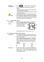
Страница 123: ...5 H Off Off M Off On L On Off Pin out The Range Status pins are photo coupled open collector outputs 17 14 15 Photocoupler input 30V max 8mA max 4 1 10 External Trigger Signal Description Pins 11 and 12 of the J1 connector are the trigger signal inputs The trigger signal is used to resume a sequence after a pause This action is useful to synchronize the execution of a sequence with another device ...

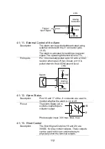
Страница 124: ...kΩ resistor when open When closed pin 10 is pulled down to the A COM ground level LSG Switch Analog connector 12 10 5V A COM 10kΩ 4 1 12 Alarm Status Description Pins 16 and 17 of the J1 connector are used to monitor whether the alarm is on or off Pin out The Alarm Status pin is a photo coupled open collector output 17 16 Photocoupler input 30V max 8mA max 4 1 13 Short Control Description The Shor...

Страница 125: ...l Output 4 1 14 1 Trigger Signal Output Description The trigger output signal is generated every time a switching operation is performed i e Dynamic mode or when a Fast or Normal Sequence is executed and the TRIG OUT parameter is enabled The trigger output signal from TRIG OUT BNC is a 4 5V pulse of at least 2us with an impedance of 500Ω The common potential is connected to the chassis potential T...

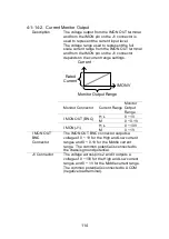
Страница 126: ...ed Current Monitor Output Range Monitor Connector Current Range Monitor Output Range I MON OUT BNC H L 0 1V M 0 0 1V I MON J1 H L 0 10V M 0 1V I MON OUT BNC Connector The IMON OUT BNC connector outputs a voltage of 0 1V for the High and Low current ranges and 0 0 1V for the Middle current range The common potential is connected to the chassis ground potential J1 Connector The voltage across pins 2...

Страница 127: ...pport Current Low Range 4 2 1 Capacity Model Single Unit 2 Units 3 Units 4 Units 5 Units LSG 175 150V 35A 175W 150V 70A 350W 150V 105A 525W 150V 140A 700W 150V 175A 875W LSG 350 150V 70A 350W 150V 140A 700W 150V 210A 1050W 150V 280A 1400W 150V 350A 1750W LSG 1050 150V 210A 1050W 150V 420A 2100W 150V 630A 3150W 150V 1680A 4200W 150V 1050A 5250W LSG 1050 LSG 2100S Boosters 150V 630A 3150W 150V 1050A...

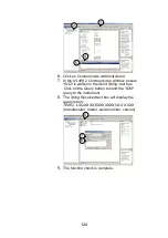
Страница 128: ... LSG 2100S booster pack is used with the LSG 1050 Ensure that wiring of sufficient gauge is used when using parallel connections If using voltage sense only connect the master to the voltage sense terminals 4 2 3 Configuration Description When using the multiple units in parallel all the basic settings are adopted from the master unit Operation 1 Make sure all load units are turned off 2 Make sure...

Страница 129: ...be used in parallel A maximum of 4 boosters can be used with a single acting as a master unit External Previous Menu Booster OFF LOAD RS232 31 Oct 2013 Parallel Operation 3 Master Configure A Value CV 35A 15V Fast Knob Parallel 9 On the slave units press Main Configure F5 Next Menu F4 Parallel F1 and set Operation to Slave When in Slave mode all keys are locked except for the Scroll wheel and Ente...

Страница 130: ...ion mode and settings on the master unit The master s settings will be used by the slave units 3 Turn the load on from the Master unit All measurements will be displayed and updated on the Master unit only 4 2 5 Disable Parallel Mode Description To disable parallel mode each unit must be set as a Master Operation 1 Turn the power off on all the units and remove the GTL 255 frame link cables 2 Turn...

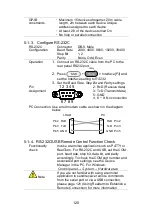
Страница 131: ...rear panel USB B port 2 Press Shift Utility Help Interface F3 and set the Interface setting to USB 3 If there is a request of the USB driver PC to recognize the instrument specify the USB CDC driver 4 In the device manager of PC if it is not assigned to the serial port is the instrument please specify the USB CDC driver updates driver 5 Please check the port number in Device Manager 5 1 2 Configur...

Страница 132: ... 8 9 2 RxD Receive data 3 TxD Transmit data 5 GND 4 6 9 No connection PC Connection Use a null modem cable as shown in the diagram below PC RxD Pin2 RxD Pin2 GND Pin5 GND Pin5 TxD Pin3 TxD Pin3 LOAD 5 1 4 RS 232C USB Remote Control Function Check Functionality check Invoke a terminal application such as PuTTY or RealTerm For RS 232C and USB set the COM port baud rate stop bit data bit and parity a...

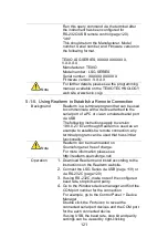
Страница 133: ...SB The following instructions apply to version 1 99 0 27 Even though Realterm is used as an example to establish a remote connection any terminal program can be used that has similar functionality Note Realterm can be downloaded on Sourceforge net free of charge For more information please see http realterm sourceforge net Operation 1 Download Realterm and install according to the instructions on ...

Страница 134: ...rol Software Flow Control options can be left at the default settings Press Open to connect to the LSG Series 7 Click on the Send tab In the EOL configuration check on the CR and LF check boxes Enter the query idn Click on Send ASCII 8 The terminal display will return the following TEXIO LSG XXXX EXXXXXXX VX XX XXX manufacturer model serial number version 9 If Realterm fails to connect to the LSG ...

Страница 135: ...TECHNOLOGY web site www texio co jp Operation 1 Start the NI Measurement and Automation Explorer MAX program Using Windows press Start All Programs National Instruments Measurement Automation 2 From the Configuration panel access My System Devices and Interfaces GP IB0 3 Press the Scan for Instruments button 4 In the Connected Instruments panel the LSG Series should be detected as Instrument 0 wit...

Страница 136: ...ensure IND is written in the Send String text box Click on the Query button to send the IDN query to the instrument 8 The String Received text box will display the query return TEXIO LSG XXXX EXXXXXXX VX XX XXX manufacturer model serial number version 6 7 8 9 The function check is complete ...

Страница 137: ... working Check to make sure that the key lock has not been activated LOCK will be shown on the panel when the screen is locked Press Shift Lock to unlock the keys The load won t turn on If you are using the load key to try to turn the load on and the load won t turn on it is possible that external control is activated and that the LoadOn In setting is set to low See page 109 for details The perfor...

Страница 138: ...r switch Gently lift the grill up from the bottom 2 Remove the filter from the grill and replace with part number PEL 010 7 2 GP IB Installation Background GP IB is an optional extra The following instructions describe how to install the optional GP IB card PEL 004 if necessary Procedure 1 Turn off the LSG Series 2 Remove the two screws holding the cover on the option bay 3 Slide the GP IB card on...

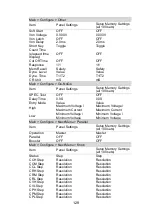
Страница 139: ... 0 W 0 W CV OFF OFF Current range H H Voltage range 150 V 150 V Load on off Load off Load off Operation mode CC CC Slew rate Maximum value of H range Maximum value of H range Preset memories Settings above in each mode Settings above in each mode Main Configure Protection Item Panel Settings Setup Memory Settings all 100 sets OCP Level Maximum value Maximum value OCP Setting LIMIT LIMIT OPP Level ...

Страница 140: ...tage Maximum Current Maximum Voltage Maximum Current Low Minimum Voltage Minimum Voltage Minimum Voltage Minimum Voltage Main Configure Next Menu Parallel Item Panel Settings Setup Memory Settings all 100 sets Operation Master Master Parallel OFF OFF Booster OFF OFF Main Configure Next Menu Knob Item Panel Settings Setup Memory Settings all 100 sets Status CCH Step Step Resolution Step Resolution ...

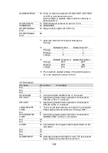
Страница 141: ...n the rear panel SUM I MON 4 Used during master slave operation Connected to SUM I MON of the J2 connector PRL IN 5 Used during master slave operation Connected to PRL OUT of the J2 connector PRL IN 6 Used during master slave operation Connected to PRL OUT of the J2 connector LOAD ON OFF CONT 7 Turns on the load with low or high TTL level signal Pulled up the internal circuit to 5 V using 10 kΩ RA...

Страница 142: ...V the maximum current is 8 mA J2 Connector Pin name Pin number Description N C 1 N C 2 N C 3 SUM I MON 4 Connect to SUM I MON of the J1 connector PRL OUT 5 Used during master slave operation Connected to PRL IN of the J1 connector PRL OUT 6 Used during master slave operation Connected to PRL IN of the J1 connector LOAD ON OFF CONT 7 Turns on the load with low or high TTL level signal Pulled up the...

Страница 143: ...rnal range switch input 1 2 Pulled up the internal circuit to 5 V using 10 kΩ ALARM INPUT 10 Activates an alarm with high or low TTL level signal input Pulled up by the internal circuit to 5 V N C 11 A COM 12 Connected to the negative load input terminal on the rear panel N C 13 N C 14 N C 15 ALARM STATUS 16 Turns on when an alarm OVP OCP OPP OTP RVP or UVP is activated or when an external alarm i...

Страница 144: ... up the internal circuit to 5 V using 10 kΩ N C 8 SLAVE RANGE CONT 9 Used during master slave operation Connected to RANGE CONT 0 of the J1 connector N C 10 N C 11 A COM 12 Connected to the negative load input terminal on the rear panel N C 13 N C 14 N C 15 ALARM INPUT 16 Activates an alarm with high or low TTL level signal input Pulled up the internal circuit to 5 V A COM 17 Connected to the nega...

Страница 145: ...oltage Load Current CC Current Value CC CV Mode When CC CV mode is enabled the unit will act as constant current load after the input voltage is greater than the user defined CV level At the CV level the unit works as a constant voltage load This mode effectively creates a voltage ceiling before the unit operates in CC mode The diagram below illustrates this CC CV Mode Load Input Voltage Load Curr...

Страница 146: ...s law This is illustrated below CR Mode Load Input Voltage Load Current CR Value CR CV Mode When CR CV mode is enabled the unit will act as constant resistive load after the input voltage is greater than the user defined CV level At the CV level the unit works as a constant voltage load This mode effectively creates a voltage ceiling before the unit operates in CR mode The diagram below illustrate...

Страница 147: ...ingly P IxV This is illustrated below CP Mode Load Current Load Input Voltage CP Value CP CV Mode When CP CV mode is enabled the unit will act as a constant power load after the input voltage is greater than the user defined CV level At the CV level the unit works as a constant voltage load This mode effectively creates a voltage ceiling before the unit operates in CP mode The diagram below illust...

Страница 148: ...ected to a constant current source This means the unit will maintain a set voltage level up to the rated power regardless of the input current When the source voltage is less than the CV level no current will flow due to a very high impedance This is illustrated below CV Mode Input Current Load Voltage CV level ...

Страница 149: ...137 7 6 Operating Area LSG 175 ...

Страница 150: ...138 LSG 350 ...

Страница 151: ...139 LSG 1050 ...

Страница 152: ...solution specifications are xN This does not include voltage settings and measured values The maximum slew rate settings also don t change N Number of units in parallel same model N 1 2 x Number of units in parallel Booster 7 7 1 Rating Model LSG 175 LSG 350 LSG 1050 Operating Voltage 1 5V 150V 1 5V 150V 1 5V 150V Current 35A 70A 210A Power 175W 350W 1050W 7 7 2 CC Mode Model LSG 175 LSG 350 LSG 1...

Страница 153: ...Vin 2 500kΩ 0 2mA Vin 2 500kΩ 0 6mA Vin 2 500kΩ Ripple RMS 5 3mA 5mA 20mA 7 P P 6 30mA 50mA 100mA 7 1 Full scale of H range 2 Vin input terminal voltage of electronic load 3 M range applies to the full scale of H range 4 When the input voltage is varied from 1 5V to 150V at a current of rated power 150V 5 Measurement frequency bandwidth 10Hz to 1MHz 6 Measurement frequency bandwidth 10Hz to 20MHz ...

Страница 154: ...mΩ OPEN L Range 0 245S 0S 4 08163Ω OPEN 0 490S 0S 2 0408Ω OPEN 1 4000S 0S 680 2721mΩ OPEN Resolution H Range 400uS 800uS 2 4mS M Range 40uS 80uS 240uS L Range 4uS 8uS 24uS Accuracy of Setting 2 H M Range 0 5 of set 3 0 5 of f s 4 Vin 5 500 kΩ L Range 0 5 of set 3 0 5 of f s Vin 5 500 kΩ 1 Siemens S Input current A Input voltage V 1 resistance Ω 2 Converted value at the input current At the input c...

Страница 155: ...75W 17 5W 3 5W 35W 10 5W 105W L Range 0 175W 1 75W 0 35W 3 5W 1 05W 10 5W Setting Range H Range 0W 178 5W 0W 357W 0W 1071W M Range 0W 17 85W 0W 35 7W 0W 107 1W L Range 0W 1 785W 0W 3 57W 0W 10 71W Resolution H Range 10mW 10mW 100mW M Range 1mW 1mW 10mW L Range 0 1mW 0 1mW 1mW Accuracy of Setting 1 0 6 of set 1 4 of f s 2 Vin 3 500kΩ 1 It is not applied for the condition of the parallel operation 2...

Страница 156: ...tion 100nA 200nA 600nA Setting 25uA us 250uA us 50uA us 500uA us 160uA us 1 6mA us Resolution 10nA 20nA 60nA Setting 2 5uA us 25uA us 5uA us 50uA us 16uA us 160uA us Accuracy of Setting 1 10 of set 5us 1 Time to reach from 10 to 90 when the current is varied from 2 to 100 20 to 100 in M range of the rated current 7 7 8 Meter Model LSG 175 LSG 350 LSG 1050 Voltmeter H Range 0 00V 150 00V 0 00V 150 ...

Страница 157: ...0ms Res 1us 10ms 30s Res 1ms Accuracy 100ppm of setting Frequency Range Freq Duty 1Hz 20kHz Frequency Resolution 1Hz 9 9Hz 0 1Hz 10Hz 99Hz 1Hz 100Hz 990Hz 10Hz 1kHz 20kHz 100Hz Frequency Accuracy of Setting 0 5 of set Duty Cycle of Setting Freq Duty 1 99 0 1 step The minimum time width is 10 us Between 1kHz and 20kHz the maximum duty cycle is limited by the minimum time width Slew Rate Setting Ran...

Страница 158: ...ution 10nA 20nA 60nA Setting 2 5uA us 25uA us 5uA us 50uA us 16uA us 160uA us Slew Rate Accuracy of setting 10 of set 5us 1 Time to reach from 10 to 90 when the current is varied from 2 to 100 20 to 100 in M range of the rated current Current Setting Range H Range 0A 35 7A 0A 71 4A 0A 214 2A M Range 0A 3 57A 0A 7 14A 0A 21 42A L Range 0A 0 357A 0A 0 714A 0A 2 142A Current Resolution H Range 1mA 2m...

Страница 159: ...10mW 10mW 100mW M Range 1mW 1mW 10mW L Range 0 1mW 0 1mW 1mW Accuracy of Setting 1 0 6 of set 1 4 of f s 2 Vin 3 500kΩ 1 It is not applied for the condition of the parallel operation 2 M range applies to the full scale of H range 3 Vin Input terminal voltage of electronic load 7 7 10 Soft Start Operation Mode CC CR and CR Selectable Time Range 1 200 ms Res 1ms Time Accuracy 30 of set 100us 7 7 11 ...

Страница 160: ...0 of the rated operating current range I range Rating overpower protection R OPP An R OPP message will be produced when the input power range is greater than 110 of the rated operating power range Front panel input rating overcurrent protection F R OCP An F R OCP message will be produced when the front panel input current range is greater than 77A Typical 7 7 13 Sequence Normal Sequence Operation ...

Страница 161: ...rts the SCPI and IEEE std 488 2 1992 command set Baud rate 2400 4800 9600 19200 38400 bps Data length 8 bit Stop bit 1 2 bit Parity bit None Odd Even USB Conforms to USB 2 0 Specifications and USB CDC ACM Sets panel functions except the power switch and reads measured values Communication speed 12 Mbps Full speed 7 7 15 Analog External Control Load on off Control Input Turn on the load with low or...

Страница 162: ...e rated current CC mode rated voltage CV mode or rated power CP mode 0 Ω to 10 kΩ correspond to maximum resistance to minimum resistance or minimum resistance to maximum resistance CR mode Current Monitor Output 10 V f s H or L range and 1 V f s M range Parallel Operation Input Signal input for one control parallel operation Parallel Operation Output Signal input for one control parallel operation...

Страница 163: ...x Insulation Resistance Primary to input terminal 500 VDC 20MΩ or more Primary to chassis 500 VDC 20MΩ or more Withstand Voltage Primary to input terminal No abnormalities at 1500 VAC for 1 minute Primary to chassis No abnormalities at 1500 VAC for 1 minute Dimensions W mm H mm D mm 213 8 124 0 400 5 213 8 124 0 400 5 427 8 124 0 400 5 427 7 127 8 553 5 Weight Approx 6 kg 7 kg 17 kg 23 kg ...

Страница 164: ...ns 7 8 1 LSG 175 LSG 350 I MON OUT TRIG OUT 1 5 150V 175W 0 35A P0 P1 P4 P7 CAL P2 P5 P8 Lock P3 P6 P9 Utility Local File 0 1 4 7 2 5 8 3 6 9 Enter Clear Shift Preset Load On Off Main Help FUNC Short 213 8 464 4 400 5 124 0 151 6 ...

Страница 165: ...P 3 P 6 P 9 Utility Loc al File 0 1 4 7 2 5 8 3 6 9 Enter Clear Shift Preset Load O n Off Mai n Help FUNC Short TRIG OUT I MON OUT 1 5 150V 1050W 0 70A 400 5 464 4 427 8 441 4 124 0 143 8 7 8 3 LSG 2100S LINK STBY 427 7 5 0 5 8 553 5 592 5 127 8 147 8 ...

Страница 166: ......
Страница 167: ...7F Towa Fudosan Shin Yokohama Bldg 2 18 13 Shin Yokohama Kohoku ku Yokohama Kanagawa 222 0033 Japan http www texio co jp ...

Отзывы: