Application Note P4097
© TeraTron GmbH
Page 15 of 21
V1.1, 07.06.01
With the length of the connection the susceptibility against EMI is increased. Also the electrical
parameters of the cable and their tolerances or drift over temperature are becoming important with
increasing length.
For architectures where 50cm are by far exceeded the use of an active antenna is recommended. The
digital signals can be carried over a large distance as susceptibility against injected noise is reduced.
5. Software Design
5.1 Timing considerations
When writing software to interface with the P4097 which is running in PLL mode without an external
clock it is important to have in mind that the antenna frequency which is the clock for the transponder,
is generated by a PLL and the frequency therefore depends on the component values and their
deviation over temperature and manufacturing tolerances.
If the resonance frequency can shift more than about 2% over tolerances and temperature it is
strongly recommended to achieve a reliable reader design to measure the actual resonance frequency
by software and do the complete read and write timing with the transponder relative to the measured
frequency.
For that reason the serial interface can be programmed with bit#3 of the command register to output
the PLL frequency divided by 32. For some transponders this is already the bit length.
The exact value for the allowed tolerance in resonance frequency depends on the used transponder.
The more stringent it’s timing requirements is or the more bits are transferred without synchronization
the lower the allowed tolerances are.
Errors due to desynchronization are hard to find and are often dependent on the data value which is
sent or received. The effect could be that some fix code transponders could not be read, depending on
their serial number, or crypt code transponders do not work with certain random numbers. Such a
“random” behaviour is not easy to debug.
To avoid such errors and to be able to use less expensive and higher tolerance components it is a
good design practice to derive all timings from the transponder clock which is the antenna frequency.
5.2 Interface requirements
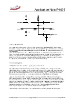
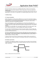
As described in the datasheet the signals CLK and IN are used to enter data into the serial interface
and do the interface reset. Because of this combined functionality it is important to control the rising
edges of both signals.
IN
ts
CLK
Figure 8.: Entering data into the serial interface

