Application Note P4097
© TeraTron GmbH
Page 21 of 21
V1.1, 07.06.01
C6
150pF
L2
10uH
5V
GND
C2
100pF
from µC
GND
GND
GND
C4
47nF
J1
Antenna
1
2
R2
4.7k
GND
C11
100nF
P4097
1
10
2
3
5
4
6
7
8
9
13
12
11
15
14
16
VSS
CLK
ANT1
DVDD
DVSS
ANT2
VDD
DEMOD_IN
CDEC_OUT
CDEC_IN
CAGND
OUT
IN
CF
CDC
EC
C5
1.5nF
C1
100pF
to µC
from µC
L1
10uH
GND
C9
100nF
C3
100pF
R1
10R
C8
150nF
C10
10nF
C7
1nF
GND
GND
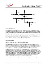
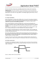
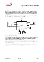
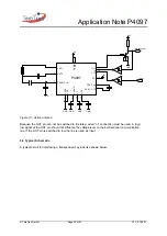
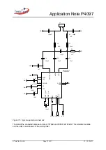
Figure 15.: Typical application schematic
The data of the connected antenna coil are L=1070µH and R=65
Ω
at 125kHz. This includes the cable
and the eddy current losses of the lock cylinder.

