Application Note P4097
© TeraTron GmbH
Page 11 of 21
V1.1, 07.06.01
GND
DEMOD_IN
1k
100pF
10uH
1.5nF
GND
100pF
ANT2
GND
ANT1
GND
10uH
68pF
10R
Antenna
100pF
100nF
1.5nF
Antenna
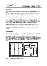
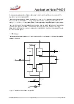
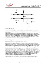
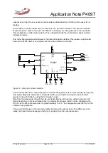
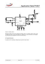
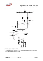
Figure 6.: EMI filter circuit
If the quality factor trimming resistor value is large enough it may be split equally on both antenna
connections and may replace the 10µH inductors. The susceptibility against interference is increased
compared to the inductor solution, especially for higher frequencies, but may be still sufficient for the
given application.
The short circuit protection is done in this example with the capacitive decoupling of both antenna
drivers. The smaller capacitor determines the resonance frequency together with the inductance of the
coil. It is a low tolerant, low temperature drift, high voltage type. The larger capacitor should be in
relation 10 to 100 times larger so that a low voltage and high tolerance type can be used. The larger
the capacitance, the lower is the influence on the resonance frequency.
3.9 Antenna diagnosis
The P4097 contains three kinds of inspecting the antenna circuit.
Both output stages are tested internally for correct voltage levels. The driven voltage level and the
actual voltage level at the output pin are compared each cycle and the output stage is switched into tri-
state mode when the output does not reach the assumed voltage. This feature protects the P- and N-
channel driver transistor against destruction by short circuit to V
SS
or V
DD
. The occurrence of these
short circuits can be read back by the connected µController through the serial shift register.
A typical current threshold for switching off the output stage is 600mA. If the short circuit happens
during normal operation it will be switched off after 4µs at the latest when running with 125kHz carrier
frequency. If the circuit is powered up into a short circuit the current will be switched off as soon as the
internal (PLL) or external (EC) clock is present. In case the chip is using its PLL the short circuit path
is interrupted after about 300µs. If the circuit has to deal with such states the power supply has to be
designed appropriate as the current can reach up to 1.5A. The power supply requirements are
reduced by inserting the series capacitor as described in the chapter above.
The drivers stay switched off until they are activated at the next writing of the serial shift register.

