Application Note P4097
© TeraTron GmbH
Page 12 of 21
V1.1, 07.06.01
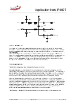
The signal at the DEMOD_IN pin does reach a certain voltage level during normal operation. It is the
antenna tab voltage decreased by an capacitive voltage divider. If this voltage is lower than a fixed
limit shown in the datasheet the input status bit is set. This indicates a broken antenna or connection
to the antenna, or in general a too low quality factor of the antenna.
The status of the phase lock loop is outputted in a third bit of the serial shift register. It shows the
mistuning of the antenna loop, which means the PLL could not lock to a frequency in a certain range.
This shows a broken or short circuited antenna connection or wrong values for inductance or
capacitance of the antenna loop, or in general a wrong resonance frequency of the antenna.
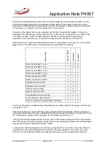
All three bits are not logical connected with each other. A single failure can cause one or more failure
flags to occur. The pattern has to be interpreted by the µController if necessary.
Failure mode
Antenna Status
Input Status
PLL
-Status
Short circuit of ANT1 to V
SS
1
X
0
Short circuit of ANT1 to V
DD
1
X
0
Short circuit of ANT2 to V
SS
1
1
1
Short circuit of ANT2 to V
DD
1
1
1
Broken connection to ANT1
0
1
1
Broken connection to ANT2
0
1
1
Capacitor value too large
0
X
1
Capacitor value too small
0
X
1
Inductor value too large
0
X
1
Inductor value too small
0
X
1
Loop resistance value too large
0
0
0
Loop resistance value too small
X
1
0
Antenna voltage is being modulated (no failure)
0
1
0
The X’s are showing an undefined status. Depending on the safety margin of the design, the bit could
be read as “0” or “1”.
If the antenna driver is switched off during communication with the transponder, the PLL will loose is
tuning state depending on the time constant determined by the external capacitor connected to the pin
CF. If the driver is switched off for a long time the PLL-Status bit will show a “1”.
Testing of the antenna status bits should only be done if the antenna voltage is at its normal constant
level. This means it shall not be tested in power down mode, during write pulses and in settling phases
because the diagnostic information might be unclear.
A more precise antenna diagnosis can be done by using the OUT pin as clock output. By setting the
data/clock bit in the serial shift register the actual PLL frequency divided by 32 can be seen at the
OUT pin. The connected µController can measure with a pulse counting or gated timer the exact

