Application Note P4097
© TeraTron GmbH
Page 17 of 21
V1.1, 07.06.01
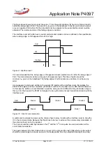
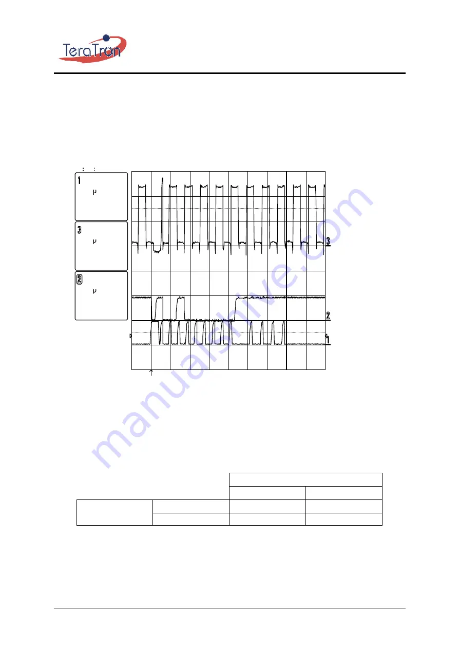
The recommended pause length depends on the written data and is described in the specification of
the P4097. Violating this pause may cause wrong status bit information. Writing the same data in the
shift register after the recommended pause duration again without a delay between the 9
th
and 10
th
clock cycle results in a correct status output.
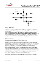
26-Jan-01
13 34 43
10
s
5.0 V
10
s
2.00 V
10
s
5.0 V
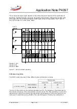
Channel 1: CLK
Channel 2: IN
Channel 3: ANT2
Figure 11.: Serial command sequence
5.3 Modes of operation
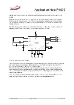
The P4097 is able to be used in three different system architectures or modes.
Clock source
Internal PLL
External clock
Direct Interface
yes
yes
µController location
Active Antenna
yes
no
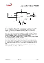
The clock for the antenna can be internally generated by a PLL. The frequency is then determined by
the resonance frequency of the antenna series resonance circuit. The other possibility is to connect an
external clock to the EC pin and drive the antenna with a fixed frequency. In this case the EC pin can
not be used to switch the meaning of bit#3 of the serial shift register. Therefore the combination of

