INSTRUMENT MANUAL
VACUUM GAUGE MODEL MM200
160Phone:(215) 947-2500 fax:(215) 947-7464 e-mail:[email protected] web site:www.televac.com
MM-200_im REV M
Page 90 of 160
TELEVAC
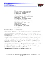
F. "FIL NUMBER (1 or 2)"
. This applies to the selection of filament only for the model 3D or 3E gauges.
G. "DE-GAS (ON or OFF)"
. This applies to de-gassing of either 3D or 3E model gauges.
H. "HOT CATHODE MODE (AUTO or SELF or BOTH)"
. This refers to the mode of operation that causes the
filament of either model 3D or 3E to turn off automatically. "AUTO" means that the controlling thermocouple
station will cause the filament to go off when a predetermined pressure is reached in the chamber. "SELF"
means that when the pressure measured by the 3D or 3E sensor reaches a predetermined point the filament will
shut off. "BOTH" means that either of these conditions will cause the filament to shut off.
I. "HC/CC CONTROL STATIONS ODD/EVEN (y, z)"
. At initialization, the station configuration is determined by
the microprocessor starting at station #1 and proceeding in an increasing direction. The first T/C or convection type
gauge sensed, "y", is assigned to control H/C and C/C gauges that are assigned odd station numbers. The next
T/C or convection type gauge detected, "z", is assigned to control the H/C andC/C gauges that are assigned even
station numbers.
J. "LEAK RATE (ON or OFF)". This shows if Leak Rate testing is in progress.
K. "PROC MARGIN = nn". This indicates how much microprocessor stack space
has not been used since power was turned on. This is an indication of
possible problems with the software. This number should not go to less than
3.
L. “0-10V
OUTPUT (ON or OFF)". This indicates whether the recorder outputs
have been disabled or not. Disabling them, if not being used, will result in a
slight improvement of the response time in the "burst" mode.
M. "RS232 SET POINTS bbbbbbbb". This indicates the set point relays that are
under control of RS232. It does not indicate if they are operated or not. Each
"b" is a bit indicated by a "1" or a "0". A "1" indicates that relay is under
RS232 control. The left hand bit corresponds to relay #1, and so forth.
N. "PARITY IS (EVEN or ODD or NONE)". This indicates the parity mode that
has been select for the modular unit.
O. "SET POINTS bbbbbbbb". This indicates the operation of the set point relays
regardless of whether they are locally or remotely controlled. If relay module
RY2 is not installed, then there are only four bits. The left-hand bit
corresponds to PCR1, and so forth.

