INSTRUMENT MANUAL
VACUUM GAUGE MODEL MM200
160Phone:(215) 947-2500 fax:(215) 947-7464 e-mail:[email protected] web site:www.televac.com
MM-200_im REV M
Page 135 of 160
TELEVAC
803 SENSORS
Specifications for the various sensors (gauge tubes) are listed in Tables 3.2 and 4.1.
804 ORDERING INFORMATION
Modular gauges may be assembled by combining several modules to form the desired multi-functional gauge.
Select the desired modules and build the model number of the gauge as shown in the example below. Typically,
setpoint relay modules are inserted first, starting from left to right, then thermocouple gauges are installed from left
to right. Finally, cold cathode gauges from right to left. Blank panels are used if there is less than a full complement
of modules. In the analog versions, the types of modules are limited by the markings on the meter (s) installed;
whereas in the digital gauge no limitations exist.
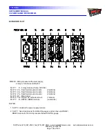
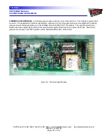
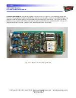
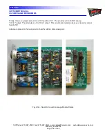
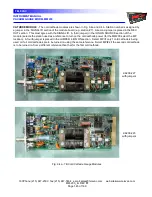
AVAILABLE MODULES: Can be placed in any of slots 1 through 6
TC = THERMOCOUPLE
CC = COLD CATHODE
2A = Two station 2A
7B = One station 7B2
7E = One station 7E
CV = CONVECTION
7F = One station 7F
4A = Two station 4A
DI = DIAPHRAGM
HC = HOT CATHODE
1E = Two station 1E
3D = Hot cathode (I
2
R degas)
3E = Hot carthode (EB degas)
S = SETPOINT RELAY
R = DIGITAL INT.
S = 4 @ 5 Amp, 120VAC R = RS232 / RS485 (SLOT 7)
B = BLANK PANELS
B1 = Full blank
B2 = 1/2 blank
FUTURE OPTIONS:
Capacitance Diaphragm Gauge (CDG), Flow Meter


