


INSTRUMENT MANUAL
VACUUM GAUGE MODEL MM200
160Phone:(215) 947-2500 fax:(215) 947-7464 e-mail:[email protected] web site:www.televac.com
MM-200_im REV M
Page 53 of 160
TELEVAC
500 SETUP
Stored parameter data may be viewed and modified by the user. Parameter values are modified by using the
UP/DOWN arrow keys. The longer the arrow keys are held down the faster the values increase or decrease.
501 INITIALIZATION
When power is applied to the instrument, an initialization program is performed. The initialization was briefly
discussed in Section 203 and consists of the following steps:
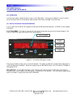
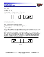
INITIAL DISPLAYS
- The front panel (shown in Fig. 2.2) is used to observe the displays and to execute the initial
"self-test" of the unit. Turn the power on by pressing the rear panel power switch to ON. The initial display shows
the word "SOFt" followed by a number indicating which software version is present (See Fig. 2.3).
This message is followed by an error code, if any errors are present (See Section 900). If no errors are present,
the initial display of two installed sensor modules appears.
When the initial display appears, the default mode is to display the non-ion type station with the lowest station
number in the right-hand display. This is usually a thermocouple, convection or diaphragm gauge. Since no cable
and/or sensor is connected, the "CAbL" message blinks. If a display does not appear, check the power outlet and
the main fuse on the rear of the unit.
The left-hand display shows the ion type station with the lowest station number if there are any ion type stations, if
not, then the next lowest station number is displayed. Typically the primary ionization station, which is cold cathode
station #7 in the example shown in Fig. 2.2 and Fig. 2.4. Since the high voltage power is off, the display reads
"OFF".
During the initialization process, the following steps take place:
1.
The station displays and the various LEDs go blank.
2.
The A/D converter is calibrated.
3.
Each station is interrogated to determine the type of sensor installed, if any. In normal
operation only those stations that are installed are measured routinely and available for
display. Also, only those stations are available for setpoint assignment.
4.
The setpoint boards are then interrogated to determine which set points are installed. Only
installed set points are available for selection during the "FUNCTION" operation. Setpoint
modules must be set up with SP identification in either 1, 2, 3, 4 or 5, 6, 7, 8 sequences
only.
5.
Setpoint selections and settings that were in effect when power was last applied are then
read from the nonvolatile memory. These selections and settings are then used as the
current ones.
6.
If any error is detected, the instrument goes into the error function routine. The
message "Err" plus a code is displayed. (See Section 502.1).
7.
The instrument then resumes normal operation with the right-hand display displaying the
reading of the first installed (lowest position number) thermocouple or convection type
gauge. These type gauges are typically used to disable the power to all ionization gauges
that are installed when the pressure exceeds a preset pressure value (typically 10 microns
for cold cathode gauges). The left-hand display shows the primary cold cathode gauge
(the one with the lowest station number).


