INSTRUMENT MANUAL
VACUUM GAUGE MODEL MM200
160Phone:(215) 947-2500 fax:(215) 947-7464 e-mail:[email protected] web site:www.televac.com
MM-200_im REV M
Page 41 of 160
TELEVAC
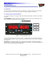
pushbuttons. The ionization gauge display flashes "OFF" until it is turned on by the controlling thermocouple
station (usually TC#1). The high voltage to the gauge tube will be off during this time.
Normally, the thermocouple station data are indicated in microns in a numerical format for pressures above 1
micron. The ionization gauge stations are indicated in Torr below 1 micron (10
-3
Torr) using an exponential format.
In the exponential format, positive and negative exponent can be used. The display of negative and positive
exponents is done as follows:
3.0 x 10
-7
is displayed as 3.0-7
3.0 x 10
+2
is displayed as 3.0E2
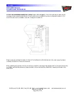
UNITS: TORR, MICRONS, MBAR, PA, PSI
- Use the UNITS pushbutton to select the desired pressure
measurement unit to be displayed. Also available is MICRONS per HR used for leak rate and, in the future,
SCC/M for flow rate display.
GAS TYPE: (N
2
or GAS)
- These abbreviations indicate the gas type that is being measured by the selected
sensor. The gas type has been selected by the operator via front panel programming using the N2/GAS
pushbutton. The alternate gas type is factory programmed and is typically argon. Display letters periodically flash
ArG
(for argon) and
He
(for helium gas). Other gas types may be available on special order.
LEAK RATE INDICATOR
- This is a trend representation of displayed data and indicates the rate of change of
pressure. Full scale is approximately 9999 microns/hour. A positive number indicates pressure increases, a
negative number indicates pressure decreases. This feature is activated via the LEAK RT pushbutton.
SETPOINT RELAY STATUS NUMBERS
- The setpoint relay status lights show the status of each relay. If the
number is illuminated, then the relay has been energized due to the pressure on the assigned sensor falling below
the "on" setpoint. These numbers are not lighted during the self-diagnostic function. They are out during the
initialization routine after power-up. Relays are located on the optional setpoint module board.
402 ERROR INDICATIONS
Using internal diagnostics, the gauge software system continuously monitors the unit to verify proper operating
conditions during power-up and normal operations. Any error conditions that are detected are displayed on the
LED in the form of an error code message reading "Err" in the data display. This display comes up automatically
after power-up or whenever the self-diagnostic test is run. The display also indicates the particular error condition
detected. Refer to Section 502.1 for a more detailed explanation of error messages.

