


3-8
3. INSTALLATION PROCEDURE FOR THE OPTIONAL EQUIPMENT
EM18-33011
3.5 Strip Module (B-4905-H-QM)
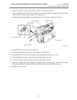
1.
Remove the top cover and left side cover (See Fig. 2-1.)
2.
Remove the operation panel. (See Fig. 3-3.)
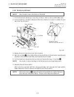
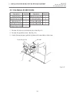
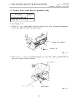
3.
Fasten the rewind paper guide to the base with the two SM-4 x 6B screws.
Fig. 3-11
(Revision Date: Sep. 29 '95)
3.5 Strip Module (B-4905-H-QM)
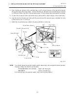
Description
Rewinder Ass'y
Rewind Full Sensor (LED)
Strip Sensor (Tr)
Strip Sensor (LED)
Rewind Paper Guide
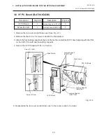
Description
Rewinder Guide Plate
Screw (FL-4x6)
Screw (SM-3x6B)
Screw (SM-4x6B)
Q'ty/Unit
1
1
1
1
1
Q'ty/Unit
1
4
1
2
SM-4x6B
Base
Rewind Paper Guide


