Monitoring of Thermo-ASIC and Printhead
Testmodes and Troubleshooting
4-22
4.5
Monitoring of Thermo-
ASIC and Printhead
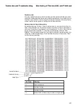
After Power On the Thermo-ASIC will be tested. Is there a problem the display will
show a bitcoded message THS ERROR XXX (XXX = Failure number from 1 trough
16). The message is active approx. 20 s and will be deleted by pressing any key.
Bit 1 = 1 (xxx = 001) low current error
Cable of printhead is broken, coil defect, contact of connector bad
Bit 2 = 1 (xxx = 002) high current error
constant current generator defect, Thermo – ASIC defect, short in coil system
Bit 3 = 1 (xxx = 004) Rref error
Printhead ID wrong, Reference resistor wrong or missing or contact failure
Bit 4= 1 (xxx = 008) Eeprom values wrong
calibrating of printhead not ok., Eeprom defect, Thermo – ASIC defect
Above mentioned failure possibilities might occur as combinations. Example: xxx = 9;
9 = 1001 binary = failure 1+4
Behavoir in case of failure:
If a THS-ERROR is recognized the ASIC will be switched off by firmware. To make
printout nevertheless possible the print will be stopped shortly at the end of the line
to protect overheating of the printhead.
4.5.1
Calibrating Values of
Thermo-ASIC and
Printhead*
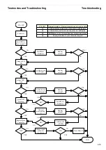
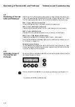
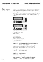
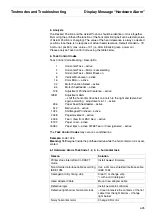
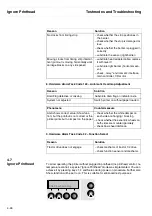
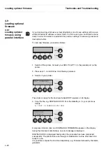
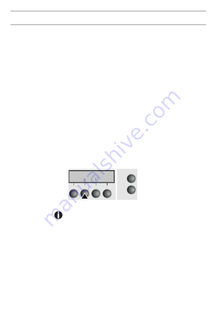
By pressing the keys ONLINE and SETUP you will enter the service menue. After that
the display changes as follows:
Printers with NDK9 and NDK9MC do not need any calibration (see Chapter 4.11).
* For printers with NDK9+ printheads only.
*
Temp.cal
Back
Next
Содержание 2365
Страница 1: ...Maintenance manual Matrix printer 2365 2380...
Страница 2: ...This page intentionally left blank...
Страница 8: ...This page intentionally left blank...
Страница 10: ...This page intentionally left blank...
Страница 20: ...This page intentionally left blank...
Страница 32: ...Mechanical Functions Functional Description 3 12 right mark mark mark...
Страница 35: ...Functional Description Electronic Functions 3 15 2365 2380 Electronic groups...
Страница 128: ...This page intentionally left blank...
Страница 134: ...Mechanical Adjustments Adjustments 6 6...
Страница 136: ...Electrical Adjustments Adjustments 6 8...
Страница 142: ...Housing Spare Parts and Schematics 7 2 7 1 Housing 7 1 1...
Страница 144: ...Basic Printer Spare Parts and Schematics 7 4 7 2 1 Basic Printer 1 3 36...
Страница 145: ...Spare Parts and Schematics Basic Printer 7 5 Basic Printer 2 3 462646...
Страница 146: ...Basic Printer Spare Parts and Schematics 7 6 Basic Printer 3 3...
Страница 147: ...Spare Parts and Schematics Basic Printer 7 7 7 2 2 Carriage RMS and Platen 72 125 138 139 136 62 11 137...
Страница 151: ...This page intentionally left blank...
Страница 152: ...Standard Tractor Assy Spare Parts and Schematics 7 12 7 3 Standard Tractor Assy 462646 134 140 17...
Страница 162: ...PMS Double Sensor Spare Parts and Schematics 7 22 7 8 PMS Double Sensor T R T R T Transmit R Receive...
Страница 164: ...Option Recognition Spare Parts and Schematics 7 24 7 10 Option Recognition...
Страница 168: ...This page intentionally left blank...
Страница 170: ...Tractor Complete Rear Tractor 2T Model 8 2 8 2 Tractor Complete 4 1...
Страница 172: ...This page intentionally left blank...
Страница 174: ...Cutting Device Option Specifications 9 2 14 6 4 12 1 5 6 11 7 13 7 8 17 2 9 3 16 15 4...
Страница 176: ...This page intentionally left blank...
Страница 177: ...2nd Front Tractor option 10 1 10 2nd Front Tractor option...
Страница 179: ...Printer Stand Overview 11 1 11 Printer Stand 11 1 Overview...
Страница 180: ...Installing the Printer Stand Printer Stand 11 2 11 2 Installing the Printer Stand 1 2 3 4...
Страница 181: ...Printer Stand Installing the Printer Stand 11 3 6 8 7 5...
Страница 182: ...Installing the Printer Stand Printer Stand 11 4 9 10...


