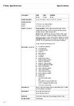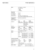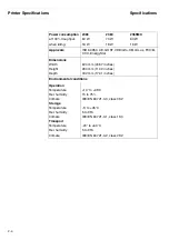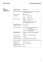
Mechanical Functions
Functional Description
3-6
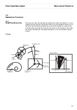
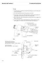
Principle
1. The sliding sleeve is pushed by turning of the switching gear over the tractor gear
on the revolving sleeve
2. The revolving gear is pushed over the guide line of the turret
3. The pressure spring, the slope at the sliding sleeve and the revolving sleeve, the
revolving sleeve is turned into next position of the sliding sleeve
4. While turning back of the switching gear the revolving sleeve will be engaged in the
position of the guide line
5. To lock into position ,,tractor 2" the switching gear is not turned back. Then the
revolving sleeve is not locked in the turret but locked in the sliding sleeve
Base
Lock position tractor 2
Lock position Single Sheet
Lock position tractor 1
Pressure
spring
Revolving Sleeve
Guide-line
Turret
Sliding
Sleeve
= Lock position
= Power
tranmission
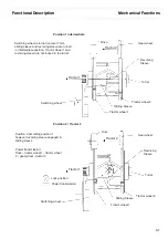
Tractor 2
Drive
Tractor wheel 2
Tractor wheel 1
Sliding Sleeve
Switching wheel
Swichting gear on level 0mm
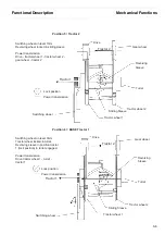
Tractor wheel locked in turret.
Revolving sleeve in position 1 of turret locked
Power transmission
Drive - tractor wheel 1 - turret - tractor 1
Revolving
Sleeve
Turret
Tractor 1
Gear wheel
Содержание 2365
Страница 1: ...Maintenance manual Matrix printer 2365 2380...
Страница 2: ...This page intentionally left blank...
Страница 8: ...This page intentionally left blank...
Страница 10: ...This page intentionally left blank...
Страница 20: ...This page intentionally left blank...
Страница 32: ...Mechanical Functions Functional Description 3 12 right mark mark mark...
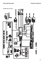
Страница 35: ...Functional Description Electronic Functions 3 15 2365 2380 Electronic groups...
Страница 128: ...This page intentionally left blank...
Страница 134: ...Mechanical Adjustments Adjustments 6 6...
Страница 136: ...Electrical Adjustments Adjustments 6 8...
Страница 142: ...Housing Spare Parts and Schematics 7 2 7 1 Housing 7 1 1...
Страница 144: ...Basic Printer Spare Parts and Schematics 7 4 7 2 1 Basic Printer 1 3 36...
Страница 145: ...Spare Parts and Schematics Basic Printer 7 5 Basic Printer 2 3 462646...
Страница 146: ...Basic Printer Spare Parts and Schematics 7 6 Basic Printer 3 3...
Страница 147: ...Spare Parts and Schematics Basic Printer 7 7 7 2 2 Carriage RMS and Platen 72 125 138 139 136 62 11 137...
Страница 151: ...This page intentionally left blank...
Страница 152: ...Standard Tractor Assy Spare Parts and Schematics 7 12 7 3 Standard Tractor Assy 462646 134 140 17...
Страница 162: ...PMS Double Sensor Spare Parts and Schematics 7 22 7 8 PMS Double Sensor T R T R T Transmit R Receive...
Страница 164: ...Option Recognition Spare Parts and Schematics 7 24 7 10 Option Recognition...
Страница 168: ...This page intentionally left blank...
Страница 170: ...Tractor Complete Rear Tractor 2T Model 8 2 8 2 Tractor Complete 4 1...
Страница 172: ...This page intentionally left blank...
Страница 174: ...Cutting Device Option Specifications 9 2 14 6 4 12 1 5 6 11 7 13 7 8 17 2 9 3 16 15 4...
Страница 176: ...This page intentionally left blank...
Страница 177: ...2nd Front Tractor option 10 1 10 2nd Front Tractor option...
Страница 179: ...Printer Stand Overview 11 1 11 Printer Stand 11 1 Overview...
Страница 180: ...Installing the Printer Stand Printer Stand 11 2 11 2 Installing the Printer Stand 1 2 3 4...
Страница 181: ...Printer Stand Installing the Printer Stand 11 3 6 8 7 5...
Страница 182: ...Installing the Printer Stand Printer Stand 11 4 9 10...

