Functional Description
Electronic Functions
3-35
3.3.22
Printhead
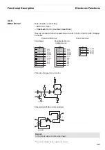
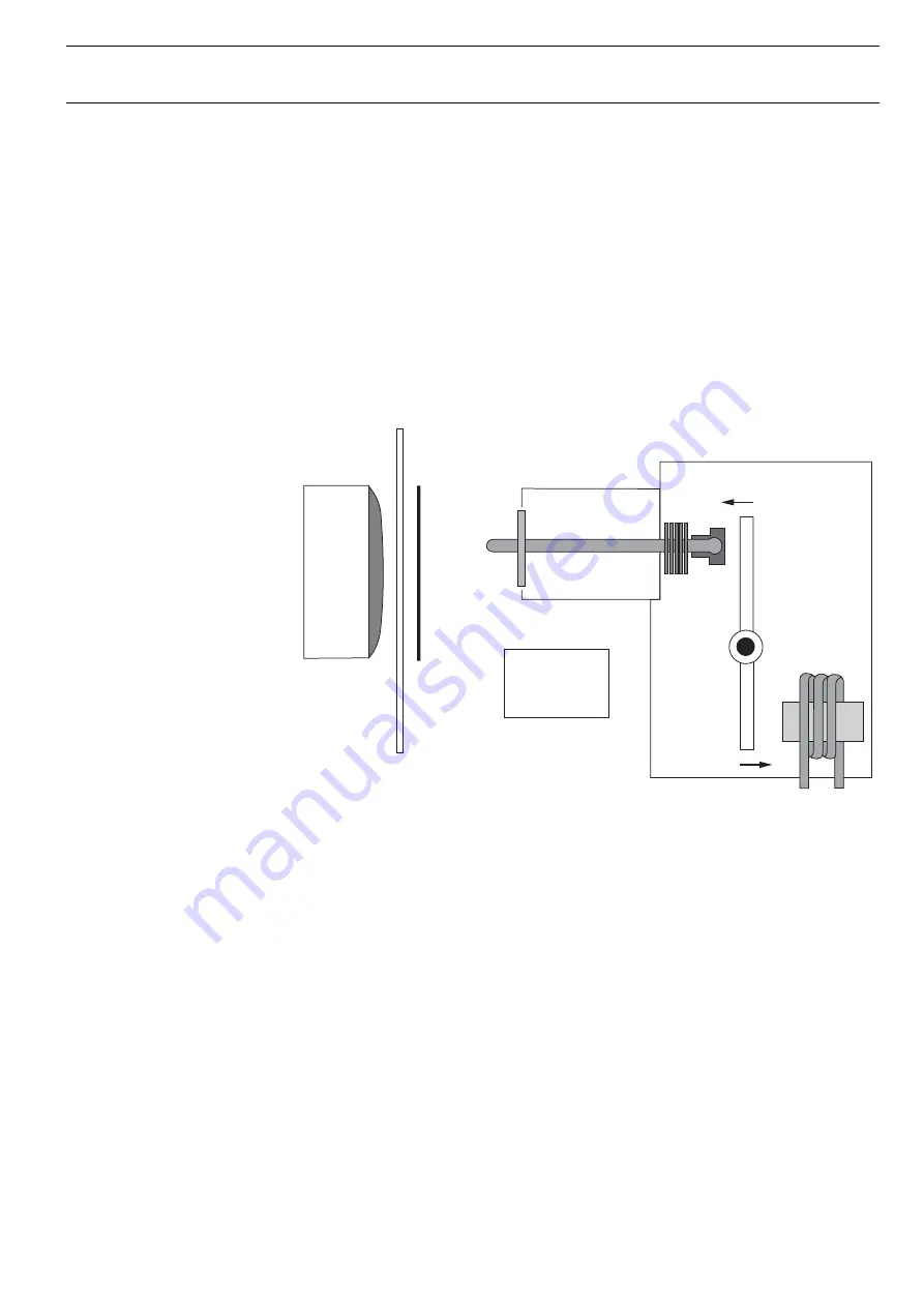
This modern ballistic printhead is driven by the needle driver section on the main
board (FT5763M, signals N1x–N24x).
General
:
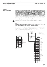
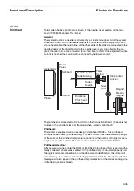
The system to shoot a needle is activated by a current through a coil of the system.
One end of each coil of the needle magnet is connected to the voltage UN (+33) V
via the head cable. The return lines of the other ends of the coils are connected to the
needle drivers of the driver board. In the needle driver chip; controlled by the pro-
gram; the return lines are connected for a short time to GND. If the expected needle
current is reached the current will be chopped by hardware control.
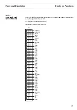
The printhead is connected to X2 and X14 on the Connection Board. (Take care not
to loosen the pull relief clamp at the plugs when replacing printhead!).
Printhead:
The printer is equipped with a new designed printhead NDK9+. This printhead
contains an EEPROM (printhead chip). This EEPROM stores the calibration settings
of the coils for the printhead temperature control and the number of firings for every
single needle (dot counter). The chip is also used for detection of the NDK9+.
Printhead detection:
After powering on the printer the ROM of the DS2433 (printhead chip) is read and the
family code and checksum is verified. If the printhead chip is detected properly and
the logic board and connection board has the correct identification, the printer will
start normally, in all other cases it will display "Hardware Alarm, Wrong Board". This
message will also appear if the printhead chip is defective or the corresponding wire
in the trailing cable is broken.
P
a
pier
P
a
per
F
a
r
bba
nd
Ri
bb
on
Needle G
u
ide
N
a
del
N
a
delführ
u
ng
Needle
Gegenl
a
ge
Pl
a
ten
Dr
u
ckkopf
Print he
a
d
B
a
lli
s
tic
F
uss
Foot
M
a
gnet
Elektro-
m
a
gnet
S
pring
Feder
Kl
a
pp
a
nker
Anchor
Содержание 2365
Страница 1: ...Maintenance manual Matrix printer 2365 2380...
Страница 2: ...This page intentionally left blank...
Страница 8: ...This page intentionally left blank...
Страница 10: ...This page intentionally left blank...
Страница 20: ...This page intentionally left blank...
Страница 32: ...Mechanical Functions Functional Description 3 12 right mark mark mark...
Страница 35: ...Functional Description Electronic Functions 3 15 2365 2380 Electronic groups...
Страница 128: ...This page intentionally left blank...
Страница 134: ...Mechanical Adjustments Adjustments 6 6...
Страница 136: ...Electrical Adjustments Adjustments 6 8...
Страница 142: ...Housing Spare Parts and Schematics 7 2 7 1 Housing 7 1 1...
Страница 144: ...Basic Printer Spare Parts and Schematics 7 4 7 2 1 Basic Printer 1 3 36...
Страница 145: ...Spare Parts and Schematics Basic Printer 7 5 Basic Printer 2 3 462646...
Страница 146: ...Basic Printer Spare Parts and Schematics 7 6 Basic Printer 3 3...
Страница 147: ...Spare Parts and Schematics Basic Printer 7 7 7 2 2 Carriage RMS and Platen 72 125 138 139 136 62 11 137...
Страница 151: ...This page intentionally left blank...
Страница 152: ...Standard Tractor Assy Spare Parts and Schematics 7 12 7 3 Standard Tractor Assy 462646 134 140 17...
Страница 162: ...PMS Double Sensor Spare Parts and Schematics 7 22 7 8 PMS Double Sensor T R T R T Transmit R Receive...
Страница 164: ...Option Recognition Spare Parts and Schematics 7 24 7 10 Option Recognition...
Страница 168: ...This page intentionally left blank...
Страница 170: ...Tractor Complete Rear Tractor 2T Model 8 2 8 2 Tractor Complete 4 1...
Страница 172: ...This page intentionally left blank...
Страница 174: ...Cutting Device Option Specifications 9 2 14 6 4 12 1 5 6 11 7 13 7 8 17 2 9 3 16 15 4...
Страница 176: ...This page intentionally left blank...
Страница 177: ...2nd Front Tractor option 10 1 10 2nd Front Tractor option...
Страница 179: ...Printer Stand Overview 11 1 11 Printer Stand 11 1 Overview...
Страница 180: ...Installing the Printer Stand Printer Stand 11 2 11 2 Installing the Printer Stand 1 2 3 4...
Страница 181: ...Printer Stand Installing the Printer Stand 11 3 6 8 7 5...
Страница 182: ...Installing the Printer Stand Printer Stand 11 4 9 10...

