


Installation 3
Taktis Fire Control Panel - Installation Manual
Man-1154-In, Revision E01.02
54 of 156
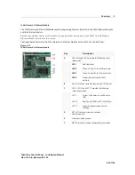
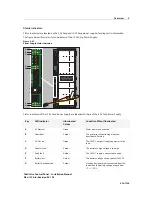
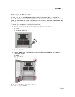
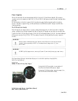
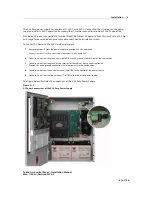
*** Locating Connector X96: Connector X96 is in a vertical position below vertical connector X80 on the Main Back
Board. Connector X96 includes connections for E, FLT, (-) and (+) of the power supply. Connector X80 includes
terminal connections for Network, RS485I/O Fire Routing O/P and Prog I/P.
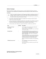
Item
Quantity
Description
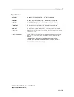
10 Conductor IDC Zone LED to
LED Cable
1 or 2
The 10 Conductor IDC Zone LED to LED Cable is a daisy-chain-
jumper that connects from the J2 connector of one LED Zone
Board to the J1 connector of the next LED Zone Board.
One 10 Conductor IDC Zone LED is required when two LED
Zone Boards are installed on the fascia of the Taktis Fire
Control Panel.
Two 10 Conductor IDC Zone LED Cables are required when
three LED Zone Boards are installed on the fascia of the Taktis
Fire Control Panel.
10 Conductor IDC Printer Cable
1
The 10 Conductor IDC Printer Cable connects from the
connector on the printer assembly to the “Printer” connector
on the LCD Main Processor Board.
Fuse Accessory Pack
1
Fuse Accessory Pack containing KD25800 series RPSM2 fuses.
FF very fast acting 12A.
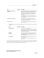
4
Acquire the following items that are not included with the Taktis Fire Control Panel, but may be required for the
installation:
Item
Quantity
Description
6WDQGE\%DWWHULHV
2
Connect two 12 VDC standby-batteries.
Reference Appendix C, Calculations to determine the Amp-Hour
capacity required to support the system or reference Appendix B,
Equipment List for the recommended model for operating under
minimum Amp-Hour conditions.
0RXQWLQJ
+DUGZDUH
1
The mounting hardware that secures the Taktis Fire Control
Panel to the premises-wall is not provided in the Taktis Fire
Control Panel packaging. Mounting screws must be 1/5” +/- 1/
50” thread diameter.
(DUWKLQJ6WUDS
1
An Earthing-Strap is required for handling Taktis Fire Control
Panel circuit boards.
The Earthing-Strap is not provided in packaging of the Taktis Fire
Control Panel.
Содержание Incite Fire S3
Страница 1: ...Taktis Operating Instructions Part Number OPIN 000004IN Revision E01 02 Date 18 09 2015...
Страница 2: ......
Страница 3: ......
Страница 4: ...D F C B A E...
Страница 5: ...I G H J...
Страница 6: ......
Страница 7: ......
Страница 8: ......
Страница 9: ......
Страница 10: ......
Страница 11: ......
Страница 12: ......
Страница 13: ......
Страница 14: ......
Страница 15: ......
Страница 16: ......
Страница 17: ......
Страница 19: ......
Страница 20: ......
Страница 21: ......
Страница 22: ......
Страница 23: ......
Страница 24: ......
Страница 25: ......
Страница 26: ......
Страница 27: ......
Страница 28: ......
Страница 29: ......
Страница 30: ......
Страница 31: ......
Страница 32: ......
Страница 33: ......
Страница 34: ......
Страница 35: ......
Страница 36: ......
Страница 37: ......
Страница 38: ......
Страница 39: ......
Страница 40: ......
Страница 41: ......
Страница 42: ......
Страница 43: ......
Страница 44: ......
Страница 45: ......
Страница 46: ......
Страница 47: ......
Страница 48: ......
Страница 49: ......
Страница 50: ......
Страница 51: ......
Страница 52: ......
Страница 53: ......
Страница 54: ......
Страница 55: ......
Страница 56: ......
Страница 57: ......
Страница 58: ......
Страница 59: ......
Страница 60: ......
Страница 61: ......
Страница 62: ......
Страница 63: ......
Страница 64: ......
Страница 65: ......
Страница 66: ......
Страница 67: ......
Страница 68: ......
Страница 69: ......
Страница 70: ...Part Number OPIN 000004IN Revision E01 02 Date 18 09 2015...
Страница 211: ......


