background image

Overview         2

Taktis Fire Control Panel  -  Installation Manual                                                                
Man-1154-In, Revision E01.02                                                                                 
                                                                                                                
                                                                                                                                                                                                                                      45 of 156

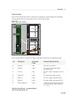
6WDWXV,QGLFDWRUV

Mains Fail

The Mains Fail LED lights green when the AC power is connected.

Heartbeat

The Heartbeat LED flashes yellow when the power supply is functioning. 

DC Out On

The DC OUT ON LED lights green when the 24V DC output is functioning.

Charger Fault

The Charger Fault LED lights yellow when the charger is not functioning.

Earth Fault

The Earth Fault lights when less than 30K Ohm exists between 24V and ground.

Battery Low

The Battery Low LED lights yellow “continuously” when the standby-battery voltage 
drops below 20.4V DC. 

Battery Disconnected

Standby-batteries are disconnected from the load when the battery voltage drops 
below 19+/- 1V DC. This occurs to protect the batteries from a deep discharge 
condition. 

A deep discharge condition can permanently damage standby-batteries. 
Preventing this condition allows standby-batteries to recharge for continued 
operation after an extended power outage.

Содержание Incite Fire S3

Страница 1: ...Taktis Operating Instructions Part Number OPIN 000004IN Revision E01 02 Date 18 09 2015...

Страница 2: ......

Страница 3: ......

Страница 4: ...D F C B A E...

Страница 5: ...I G H J...

Страница 6: ......

Страница 7: ......

Страница 8: ......

Страница 9: ......

Страница 10: ......

Страница 11: ......

Страница 12: ......

Страница 13: ......

Страница 14: ......

Страница 15: ......

Страница 16: ......

Страница 17: ......

Страница 18: ...Panel Tests Disable Zones Test Zones View Devices User Controls Panel Tests Disable All Sounders Panel Tests Disable All Plant Outputs Panel Tests Panel Tests Lamp Buzzer Test Display Test Disable Pa...

Страница 19: ......

Страница 20: ......

Страница 21: ......

Страница 22: ......

Страница 23: ......

Страница 24: ......

Страница 25: ......

Страница 26: ......

Страница 27: ......

Страница 28: ......

Страница 29: ......

Страница 30: ......

Страница 31: ......

Страница 32: ......

Страница 33: ......

Страница 34: ......

Страница 35: ......

Страница 36: ......

Страница 37: ......

Страница 38: ......

Страница 39: ......

Страница 40: ......

Страница 41: ......

Страница 42: ......

Страница 43: ......

Страница 44: ......

Страница 45: ......

Страница 46: ......

Страница 47: ......

Страница 48: ......

Страница 49: ......

Страница 50: ......

Страница 51: ......

Страница 52: ......

Страница 53: ......

Страница 54: ......

Страница 55: ......

Страница 56: ......

Страница 57: ......

Страница 58: ......

Страница 59: ......

Страница 60: ......

Страница 61: ......

Страница 62: ......

Страница 63: ......

Страница 64: ......

Страница 65: ......

Страница 66: ......

Страница 67: ......

Страница 68: ......

Страница 69: ......

Страница 70: ...Part Number OPIN 000004IN Revision E01 02 Date 18 09 2015...

Страница 71: ...Power Intelligence with a sense of feeling Taktis Fire Control Panel Installation Manual Man 1154 In Revision E01 02 Issue Date September 2015...

Страница 72: ...ldings specific to the country of use ii Codes of practice iii Statutory requirements iv Any instructions specifically advised by the manufacturer Only fire rated and shielded cable should be used Not...

Страница 73: ...ectromagnetic Compatibility Directive 2004 108 EC BS EN55022 1998 Emissions Spur BS EN50130 4 1996 A2 2003 Immunity Product Family Standard Additional functions provided that are not covered by AS7240...

Страница 74: ...s ii Codes of practice iii Statutory requirements iv Any instructions specifically advised by the manufacturer According to the provisions of the Act you are therefore requested to take such steps as...

Страница 75: ...lation Manual Man 1154 In Revision E01 02 Copyright 2015 by Incite Fire Pty Ltd All rights reserved QFLWH LUH LV D UHJLVWHUHG WUDGHPDUN RI QFLWH LUH 3W WG OO RWKHU SURGXFW RU VHUYLFH QDPHV DUH WKH SUR...

Страница 76: ...livery 3 Jurisdiction 4 Security Charges 4 Purpose of Credit 4 Formation of Contract 4 Retention of Title 5 Risk 5 Warranty 6 Cancellation 7 Claims 7 Copyright and Patents 7 Indemnity 7 Provision of F...

Страница 77: ...splay 14 Left Panel Indicators 15 Right Panel Indicators 15 Main Back Board 16 LCD Main Processor Board 31 Required Circuit Boards 33 Optional Circuit Boards and Assemblies 37 Taktis Vision Unit 42 Po...

Страница 78: ...necting Standby Batteries 62 Connecting and Dressing Cabling 65 Power Supplies 66 Circuit Boards 72 Configuring the Main Back Board 72 Installing Circuit Boards 73 DIP Switch Settings 75 DIP Switch Se...

Страница 79: ...s 101 Replacing Internal Components 105 Appendix A Specifications Electrical 107 AC Line Ratings 107 Power Supply 107 Power Supply Input Output Ratings 108 Earth Fault Indication 109 System Power 109...

Страница 80: ...mentary Devices 125 Appendix B Equipment List Models of the Fire Control Panel 127 Taktis Fire Control Panel 128 Replacement Parts 128 Appendix C Calculations Current Loading 131 Determining the Total...

Страница 81: ...Contents YL Taktis Fire Control Panel Installation Manual Man 1154 In Revision E01 02 This page intensionally left blank...

Страница 82: ...e Taktis Fire Control Panel Models of this fire control panel support Hochiki loop protocol This section describes Using This Manual Related Documentation Document Conventions If You Need Help Contact...

Страница 83: ...manual Section 1 Introduction provides document conventions the technical help line repair and return information Section 2 Overview provides a summary features of the Taktis Fire Control Panel Secti...

Страница 84: ...ktis Fire Control Panels are third party approved to the required European product standards AS7240 2 and AS7240 4 and comply with the standard for assessment of compatibility of fire detection system...

Страница 85: ...igure below illustrates the normal standby condition of the touch panel display Figure 2 3 Normal Standby Condition of Touch Panel Display Key Description A Left LED Indicators B Right LED Indicators...

Страница 86: ...w illustrates right panel indicators Figure 2 5 Right Panel Indicators Key LED Indicator Illuminated Colour A Fire Red B General Fault Amber C System Fault Amber D General Disablement Amber E Fire Pro...

Страница 87: ...in Back Board Figure 2 8 Main Back Board Key Designation Key Designation A Sounder and AUX 24V terminals G Monitored input and output terminals B Relay terminals H Ribbon cable connectors C Cable tie...

Страница 88: ...The figure below illustrates Ribbon Cable Connectors of the Main Back Board Figure 2 9 Ribbon Cable Connectors Key Designation Key Designation A LCD Main Processor Board Connector J13 D Ancillary RS23...

Страница 89: ...pur monitored outputs Sounder circuits 1 to 4 can be configured as two Loop or two Spur and one Loop output The figure below illustrates the Sounder and AUX 24V terminals of the Main Back Board Figure...

Страница 90: ...156 5HOD 7HUPLQDOV The figure below illustrates Relay Terminals of the Main Back Board Figure 2 11 Relay Terminals Field Terminals Designation Field Terminals Designation NO C and NC Fault Relay NO C...

Страница 91: ...l Slot Connectors Key Designation Key Designation A Slot A for System Board A Module E Slot E for Dual Loop Module or I O Modules B Slot B for System Board B Module F Slot F for Dual Loop Module or I...

Страница 92: ...oard Circuit Board slots C D E and F correspond to terminals C D E and F of the Main Back Board Circuit Board slots A and B do not contain corresponding letting on field terminals of the Main Back Boa...

Страница 93: ...ops 1 and 2 Figure 2 14 Board Slot C Terminals of Loops 1 and 2 Board Slot D The figure below illustrates the Board Slot D terminals of loops 3 and 4 Figure 2 15 Board Slot D Terminals of Loops 3 and...

Страница 94: ...5 6 and I O Figure 2 16 Board Slot E Terminals of Loops 5 6 and I O Board Slot F The figure below illustrates the Board Slot F terminals of Loops 7 8 And I O Figure 2 17 Board Slot F Terminals of Loop...

Страница 95: ...vision E01 02 24 of 156 DEOH 7LH ROGHUV Cable tie holders of the Main Back Board provide C shaped slots to form and secure cables WR WKH VXUIDFH RI WKH 3 ZLWK FDEOHV WLHV The figure below illustrates...

Страница 96: ...7HUPLQDOV The figure below illustrates Extension Board Power Terminals of the Main Back Board Figure 2 19 Extension Board Power Terminals These terminals are used for factory wiring purposes only Fie...

Страница 97: ...85 networking for Loop wiring RS485 I O Provides ancillary RS485 input and output for Loop wiring FIRE ROUTING O P Provides 24 volt output whenever the fire control panel is in a fire condition The Fi...

Страница 98: ...tory wiring purposes only The figure below illustrates Power Supply Terminals of the Main Back Board Figure 2 21 Power Supply Terminals Field Terminals Description E Earth terminal connection FLT Term...

Страница 99: ...ol Panel Installation Manual Man 1154 In Revision E01 02 28 of 156 0V Terminals The figure below illustrates 0V Terminals of the Main Back Board Figure 2 22 0V Terminals Field Terminals Description 0V...

Страница 100: ...or The figure below illustrates the Power Supply Fault Signalling Connector of the Main Back Board Figure 2 23 Power Supply Fault Signalling Connector Field Terminals Description Power Supply Fault Si...

Страница 101: ...vide monitored 24V DC voltage with reversing outputs The Extinguisher output provides a 3K3 resistance under normal conditions and a 680R resistance when activated All inputs require a 3K3 monitoring...

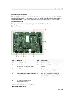
Страница 102: ...Figure 2 25 Connectors and Ports Key Description Key Description A Auxiliary RS232 port 1 F RS232 thermal Taktis Printer connection B USB A Used for memory device such as pen drives or other mass sto...

Страница 103: ...re below illustrates switches LED indicators and the internal buzzer of the LCD Main Processor Board Figure 2 26 Switches LED Indicators and The Internal Buzzer Key Description Key Description A Memor...

Страница 104: ...Loop Module for minimum operation Minimum operation describes the Taktis Fire Control Panel as an operating fire control panel All circuit boards of the Taktis Fire Control Panel are field replaceable...

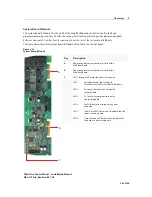
Страница 105: ...Board A Module of the Taktis Fire Control Panel Figure 2 28 System Board A Module Key Description A Edge connector for termination at slot A of the Main Back Board B Edge connector for termination at...

Страница 106: ...s Fire Control Panel Figure 2 29 System Board B Module Key Description A Edge connector for termination at slot B of the Main Back Board B Edge connector for termination at slot B of the Main Back Boa...

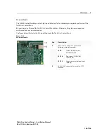
Страница 107: ...illustrates the Dual Loop Module of the Taktis Fire Control Panel Figure 2 30 Dual Loop Module Key Description A LED D8 through LED D11 provide the following status information LED D8 Heart Beat for P...

Страница 108: ...anels and Taktis Vision units Taktis Fire Control Panels can be configured for master slave multiple master slave or peer to peer connections and receive events from other Taktis Fire Control Panels i...

Страница 109: ...ktis Fire Control Panel allows Ethernet settings to be managed and configured from any remote location The figure below illustrates the Ethernet Module of the Taktis Fire Control Panel Figure 2 34 Eth...

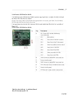
Страница 110: ...of the Taktis Fire Control Panel Figure 2 36 Taktis Network IFAM Interface Module Key Description A LED 1 through LED 8 provide the following status information LED 1 Red Heartbeat LED 2 Green Comms...

Страница 111: ...Taktis Fire Control Panel Figure 2 37 Taktis Network Ethernet Module Key Description A LED 1 through LED 4 provide the following status information LED 1 Red Heartbeat LED 2 Green Comms Tx for Taktis...

Страница 112: ...ription A LED 1 through LED 8 provide the following status information LED 1 Red Heartbeat LED 2 Green Comms Tx for Taktis network LED 3 Green Comms Rx for Taktis network LED 4 Yellow Internal fault f...

Страница 113: ...fe safety systems available today The Taktis Vision Unit is a full function fire alarm repeater that is configurable and application flexible for use in hospital nursing stations and elevator alarms T...

Страница 114: ...f the Taktis Vision Unit Figure 2 40 Connection Features of the Taktis Vision Unit Key Description Key Description A General purpose I O interface G Configuration write enable switch B SD card additio...

Страница 115: ...he standby battery voltage drops below 19 1V DC A deep discharge can cause permanent damage to standby batteries Preventing this condition allows standby batteries to recharge for continued operation...

Страница 116: ...he charger is not functioning Earth Fault The Earth Fault lights when less than 30K Ohm exists between 24V and ground Battery Low The Battery Low LED lights yellow continuously when the standby batter...

Страница 117: ...evision E01 02 46 of 156 The figure below illustrates the 5 25 Amp Power Supply of the Taktis Fire Control Panel Figure 2 41 5 25 Amp Power Supply The figure below illustrates the 10 25 Amp Power Supp...

Страница 118: ...ed B Heartbeat Amber The processor is functioning when the heartbeat is flashing C DC Out on Green The 24V DC output is supplying power to the load D General fault Amber The battery charge voltage is...

Страница 119: ...Volt free changeover contact programmable Alarm Relay Volt free changeover contact programmable Programmable Relay 1 Volt free changeover contact Programmable Relay 2 Volt free changeover contact Prog...

Страница 120: ...ble RS232 port 2 for ancillary devices Feature Description Auxiliary Connector Connector for providing additional detection loops and I O modules Network Card Connector Supports up to 128 panels throu...

Страница 121: ...Ah two to eight loop Feature Description Events Taktis Fire Control Panels provide up to 9999 events Resolution Taktis Fire Control Panels provide one second resolution Filterable Taktis Fire Control...

Страница 122: ...f the Taktis Fire Control Panel to the premises wall 1 0 Thread cabling into the cabinet and secure it to the terminals of the Taktis Fire Control Panel 1 1 Re attach the back plate to the Taktis cabi...

Страница 123: ...ntrol Panel All models of the Taktis Fire Control Panel contain the 5 25 Amp or 10 25 Amp Power Supply Main Back Board 1 The Main Back Board of the Taktis Fire Control Panel contains slots for six cir...

Страница 124: ...25 A or 10 25 A Power Supply to the J18 connector of the Main Back Board Battery Jumper Lead 1 The Battery Jumper Lead connects from the terminal of standby battery 1 to the terminal of standby batter...

Страница 125: ...onductor IDC Printer Cable 1 The 10 Conductor IDC Printer Cable connects from the connector on the printer assembly to the Printer connector on the LCD Main Processor Board Fuse Accessory Pack 1 Fuse...

Страница 126: ...t include the operating constraints of the system to maintain continuous signal monitoring and reporting Operating constraints are based on the current driving capability of the Taktis Fire Control Pa...

Страница 127: ...e mounted in an accessible position as agreed with the end user The unit must not be mounted in another enclosure or near sources of excessive heat The Taktis Fire Control Panel is intended for indoor...

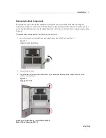
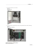
Страница 128: ...of the fire control panel The Back Plate contains the Main Back Board the 5 25 Amp or 10 25 Amp Power Supply and grounding terminals To remove these components of the Taktis Fire Control Panel 1 Inse...

Страница 129: ...1154 In Revision E01 02 58 of 156 4 Open the fascia of the Taktis Fire Control Panel Figure 3 4 Opening the Fascia 5 Disconnect four ground jumper cables from the lid and leave the opposite cable ends...

Страница 130: ...fire control panel Return the four hinge pins to the hinges of the Cabinet Box for safekeeping Figure 3 7 Removing Hinge Pins of the Fascia To remove the Fascia from the Cabinet Box 1 Pull the head o...

Страница 131: ...and the Standby Batteries To remove the Cabinet Lid from the Cabinet Box 1 Pull the head of the upper hinge pin A away from the hinge assembly using needle nose pliers 2 Brace the top corner of the ca...

Страница 132: ...rol Panel Feeding Cable Remove the appropriate number of knockouts in the positions required to suit the circuits that connect to the fire control panel and fit suitable EMC rated cable glands Referen...

Страница 133: ...her cabling into cabinet holes on the opposite side of the AC power cabling Remove additional knockout holes directly adjacent to this knockout hole to provide space for more cabling 1 Replace the bac...

Страница 134: ...nt terminals of the standby batteries so that the positive terminal of one standby battery is facing the negative terminal of the other 3 Connect the black wire of the power supply to the negative ter...

Страница 135: ...elow illustrates a marine battery bracket installation on the Taktis Fire Control Panel Figure 3 12 Marine Battery Brackets 1 Place a marine battery bracket on top of one of the standby batteries in t...

Страница 136: ...the ribbon cable from the Host I F J5 connector of the power supply to the J18 connector of the Main Back Board to connect Host I F wiring of the power supply to the Main Back Board The figure below i...

Страница 137: ...the 5 25 Amp Power Supply with the Taktis Fire Control Panel Confirm that the 5 25 Amp Power Supply is set for 230 VAC before operating at 230 VAC Permanent damage of the power supply will result if t...

Страница 138: ...p Power Supply The figure below illustrates AC connections of the 5 25 Amp Power Supply Figure 3 15 AC Power Connections of the 5 25 Amp Power Supply 1 Remove Jumper J1 from the power supply to provid...

Страница 139: ...les below describe Dip Switch settings 1 through 4 of the 5 25 Amp Power Supply Switch setting 3 is not used on the 5 25 Amp Power Supply Switch 1 Switch 2 Description Off Off Recommended for standard...

Страница 140: ...minal block TB6 Protect AC power to branch circuits with a 20 Amp anti surge fuse and include an accessible disconnect device or isolation switch To connect AC power to the 10 25 Amp Power Supply The...

Страница 141: ...test and fault reporting Switch 1 Operating Mode Description On Special Application Mode Reference The Special Application Mode Table of this Section for information concerning the operation of this s...

Страница 142: ...ure 3 20 Dip Switches of the 10 25 A Power Supply SW1 SW2 SW3 SW4 Battery Mfr Battery Size Ground Fault Detection Impedance Test Intervals Battery Missing Fault ON ON ON ON Reserved for future use ON...

Страница 143: ...emblies Of The Cabinet Box The Main Back Board contains connector slots A through F Operation of the Taktis Fire Control Panel requires that one Dual Loop Module is fitted in slots C D E or F to meet...

Страница 144: ...aktis Fire Control Panel The LCD Main Processor Board can operate a maximum of three Zone LED Boards One Zone LED Board provides 48 LED indicators Three LED Zone Boards provide 144 LED indicators Inst...

Страница 145: ...for instructions describing the removal of circuit boards 3 Remove the circuit board from the protective packaging using adequate electrostatic protection 4 Point the conductor side of the circuit boa...

Страница 146: ...circuit boards does not impact operation but each circuit board must be assigned a separate address The figure below illustrates binary addresses 1 to 15 Figure 3 26 Binary Addresses DIP Switch Settin...

Страница 147: ...ion A on the Main Back Board and System Board B Module must connect to slot position B on the Main Back Board The figure below illustrates slot position and field terminal assignments on the Taktis Fi...

Страница 148: ...tch off power at the mains 2 Open the lid of the Taktis Fire Control Panel so that the LCD Main Processor Board is accessible 3 Place a jumper across LK1 and LK2 to provide a 120 Ohm EOLR in the last...

Страница 149: ...of the IFAM Interface Module Connecting Loop Circuits Connect Loop circuits to terminal strip X32 of the Taktis Fire Control Panel Terminate unused Loops of the Taktis Fire Control Panel with zero ohm...

Страница 150: ...nnections Reference manufacturer specifications for Sensor connections The loop termination jumpers shown are provided in Resistor Kit 8 Zero Ohm Reference Appendix A for wire gage and length requirem...

Страница 151: ...tallation that does not contain output devices Perform an addressable loop installation where output devices are in one zone Perform an addressable loop installation where output devices are in differ...

Страница 152: ...l Reference Appendix C Calculations to determine wire length requirements for your application 1 Connect Sounders and End Of Line Devices to the sounder channel 2 Connect End Of Line Devices to unused...

Страница 153: ...able Characteristics Relay Contacts The Taktis Fire Control Panel contains five programmable relays that provide volt free changeover on terminal strip X1 These relays include Each volt free changeove...

Страница 154: ...erence Appendix A Specifications for cabling type length and load for this output connection Configure this output using the touch screen menu of the Taktis Fire Control Panel Set configurations in th...

Страница 155: ...Terminals of the PROG I P are located on vertical terminal strip Y1 and are designated The figure below illustrates the PROG I P terminals Figure 3 34 The PROG I P Terminals Terminal Designation Condi...

Страница 156: ...does not operate as described above 1 Apply AC power to the Taktis Fire Control Panel from the mains 2 Check that the AC Normal LED is illuminated on the Power Supply Reference Section 2 Overview for...

Страница 157: ...s on field terminals of the Taktis Fire Control Panel During the Lean Panel function internal connections to field terminals of the Taktis Fire Control Panel separate circuit contact The fire control...

Страница 158: ...hen fault conditions are not reported to the Taktis Fire Control Panel Figure 3 36 Fire System Normal Fire Brigade Panel The Fire Brigade Panel displays when the cabinet lid of the Taktis Fire Control...

Страница 159: ...nel display of the menu Panel Tests include the Lamp Buzzer Test and the Display Test Lamp Buzzer Test Perform the Lamp Buzzer Test to confirm operation of indicator lamps and the buzzer of the Taktis...

Страница 160: ...Manual Man 1154 In Revision E01 02 89 of 156 3 Press Lamp Buzzer Test The Tests window is displayed while the internal buzzer of the fire control panel sounds and all indicator lamps light for 5 secon...

Страница 161: ...ual Man 1154 In Revision E01 02 90 of 156 Display Test The Display Test confirms operation of the touch panel display To perform the Display Test 1 Press the User Controls tab on the Fire Brigade Pane...

Страница 162: ...rol Panel Installation Manual Man 1154 In Revision E01 02 91 of 156 3 Press Display Test 4 Press Continue to begin the display test Tap the touch panel display to cycle through blank raster colours of...

Страница 163: ...Version File manager LED Controller I O Board Controller Configuration Manager and the Event Log View System Information to determine the operating status of the Taktis Fire Control Panel To view sys...

Страница 164: ...to determine status of initiating devices signaling line circuits and notification appliances To view the Event Log of the Taktis Fire Control Panel The System Information window is displayed The figu...

Страница 165: ...tion Manual Man 1154 In Revision E01 02 94 of 156 2 Press View Event Log on the User Controls window 3 Press More Details to display additional information about the posted event message The figure ab...

Страница 166: ...dby Batteries To remove the existing standby batteries Installing the Standby Batteries To install the replacement standby batteries Reference Section 3 Installation for more information describing th...

Страница 167: ...will not provide the 24 volts required for operating the Taktis Fire Control Panel in a standby condition Replacing Fuses The Taktis Fire Control Panel contains a 10 Amp battery fuse and a 3 Amp powe...

Страница 168: ...isconnect the black cable from the negative terminal of Battery 2 5 Disconnect the opposite end of the black cable from the negative terminal of the power supply Battery connector 6 Disconnect the jum...

Страница 169: ...Replace the 3 Amp Power Supply Fuse by removing it from the fuse housing contained on the circuit board of the power supply Install the replacement fuse in the fuse housing and then test the power sup...

Страница 170: ...must be taken to select the correct one when fitting replacements 1 Turn off the main breaker that feeds AC power to the fire control panel 2 Locate the housing containing the 3 Amp fuse Reference Fig...

Страница 171: ...ousing 4 Press the upper housing on the lower housing until the halves snap together 5 Restore AC power to the power supply of the fire control panel 6 Monitor the touch panel display and LED indicato...

Страница 172: ...ntains the LCD Main Processor Board and Zone LED indicators of the fire control panel The Back Plate contains the Main Back Board the 5 25 Amp or 10 25 Amp Power Supply and grounding terminals To remo...

Страница 173: ...2 of 156 3 Open the fascia of the Taktis Fire Control Panel and then re insert the screws into the box for safekeeping Figure 4 4 Opening the Fascia 4 Disconnect four earthing jumper cables from the l...

Страница 174: ...of the fire control panel Return the four hinge pins to the hinges of the Cabinet Box for safekeeping Figure 4 7 Removing Hinge Pins of the Fascia To remove the Fascia from the Cabinet Box 1 Pull the...

Страница 175: ...teries 9 Remove the Standby Batteries from the base of the Cabinet Box To remove the Cabinet Lid from the Cabinet Box 1 Pull the head of the upper hinge pin A away from the hinge assembly using needle...

Страница 176: ...ernal Component Connections 0DLQ 3URFHVVRU RDUG RQH RDUG 7DNWLV 3ULQWHU WKHUQHW 0RGXOH 0DLQ DFN RDUG 6 VWHP RDUG 0RGXOH XDO RRS 0RGXOH DQG XDO RRS 0RGXOH DQG 5HTXLUHG 6ORW VVLJQPHQWV 2SWLRQDO 6ORW VVL...

Страница 177: ...Maintenance and Repair 4 Taktis Fire Control Panel Installation Manual Man 1154 In Revision E01 02 106 of 156 This page intentionally left blank...

Страница 178: ...of standby batteries at battery connections of the 5 25 Amp or 10 25 Amp power supply All powered outputs shall be monitored for weak open and short circuit as described by clauses 5 3 4 1 and 5 3 4...

Страница 179: ...um 30V DC maximum Load output current 5 25A maximum or 10 25A maximum Ripple Voltage 1 V Maximum Imax a Rated maximum output current which can be supplied continuously for the 5 25 Amp and 10 25 A Pow...

Страница 180: ...umber of active zones and the number of zones in the extinguishant state Standby and Alarm Current Standby and Alarm Currents are provided below for 115 VAC and 230 VAC models of the 5 25 A and 10 25...

Страница 181: ...for standby and alarm when battery current is less than 30 mA 680 mA 24 VDC 760 mA 24 VDC Battery current for standby and alarm when power failure condition occurs on the AC line Loops Standby mA Ala...

Страница 182: ...ent Loops Standby mA Alarm mA Description 2 176 mA 230 VAC 181 mA 230 VAC Line current for standby and alarm when battery current is less than 30 mA 550 mA 24 VDC 620 mA 24 VDC Battery current for sta...

Страница 183: ...ly 1 25 A maximum 8 Amp Power Supply 2 25 A maximum Battery Standby Current 0 080 A in mains failure Standby Battery Charging Two standby batteries wired in series Battery Charging Voltage 26 4VDCat 4...

Страница 184: ...Control Panel can include all or part of the following loads The display of the LCD Main Processor Board is dimmed Loads Standby Current Alarm Current FACP 5 25 A Power Supply 78 mA 78 mA FACP 10 25 A...

Страница 185: ...Minute Fire Rated Cables Available Core Sizes Firecel SR 114H 1 0mm2 1 5mm2 Draka Firetuf FT30 1 0mm2 1 5mm2 IDH Kilflam 2000 1 0mm2 1 5mm2 2 5mm2 Pirelli Prysmian FP200 Gold 1 0mm2 1 5mm2 2 5mm2 Tyc...

Страница 186: ...p Ratings The following ratings represent Loops 1 through 8 of the Taktis Fire Control Panel Parameter Description Serial Data Connection 2 core RS485 Up to 1150 metres total cable length Maximum Term...

Страница 187: ...rsing DC Short Circuit Threshold 130 Ohms 20 Maximum line voltage drop 2 VDC S2 24 VDC 2 5 A programmable for continuous power synchronisation and power drop on reset Fused Electronic programmable fus...

Страница 188: ...ammable Not monitored 30 VDC 1 A maximum Volt free change over contact NO C and NC ALARM RELAY Power Factor 1 0 Relay Function Common Programmable Not monitored 30 VDC 1 A maximum Volt free change ove...

Страница 189: ...ations Fire Routing Serial I O The Fire Routing I O is programmable Fire Routing O P The monitored output of the Fire Routing O P is reverse polarity and requires a 10K Ohm EOLR Fault Routing O P Term...

Страница 190: ...event capacity 1 second resolution Filterable and printable Detection Loops 2 to 8 added 2 at a time K758 Dual Loop Modules Relays Fault Fire Alarm Programmable 1 and Programmable 2 are programmable...

Страница 191: ...of 156 Parameter Description USB Host Port USB Type A USB Device Port USB type B Fire Routing Output Monitored Fire Routing Input Monitored Fault Routing Output Monitored Fault Routing Input Monitored...

Страница 192: ...50 mm TS3 Models 560 mm x 1060 mm x 230 mm Construction TS2 and TS3 Models Features include TS2 cabinet models are 1 2 mm mild sheet steel enclosures TS3 cabinet models are 1 5 mm mild sheet steel enc...

Страница 193: ...s top 2 M20 knockout left side and right side towards top TS3 Models Knockouts include 7 M20 knockouts top and bottom 2 M25 knockouts top and bottom 6 M25 knockouts back of box towards top 1 M20 knock...

Страница 194: ...5 A trip after 50 ms and fixed constant current limit of 3 3 A Current trip can beset from 0 5 A to 2 5 A Time to trip can be set from 50 ms to 250 ms Fixed constant current limit of 3 3A Sounder 1 an...

Страница 195: ...24VDC supply rated at 1 Amp AUX 24 Output 2 24VDC supply rated at 1 Amp Fire Routing Output 0V output switches to 24V fused at 100 mA requires End Of Line EOL diode Fault Routing Output 24V output swi...

Страница 196: ...charge 28V 2V Maximum ripple current Mains powered models only 200 mV Battery type Yuasa NP Mains powered models only Two 12 Volt 1 9 Ah sealed lead acid in series Battery charge voltage Mains powered...

Страница 197: ...of units on the RS485 network 127 repeaters Parameter Description Size 235mm x 170mm x 53mm Display Full colour 800 x 480 LCD with resistive touch screen and automatic backlight dimming Construction...

Страница 198: ...re Control Panel Installation Manual Man 1154 In Revision E01 02 127 of 156 Models of the Fire Control Panel The following product configuration describes model types of the Taktis Fire Control Panel...

Страница 199: ...external loads with 8 Amps and reserves 1 25 Amps for charging the standby batteries Current limits are provided in Appendix A Specifications for circuit connections of the Taktis Fire Control Panel...

Страница 200: ...nection to verify that the summed level is below the current limit value 4 Add the device load currents together that were obtained for each of the circuit connections 5 Add the Total Device Load to t...

Страница 201: ...ply battery charger with a total power rating of 280 Watts approx 10 A Larger or dual power supplies shall be required for panels with more than 10 loops and with more than 48 hour standby 1 Identify...

Страница 202: ...olts is necessary on the detection loops in order to maintain a threshold above the minimum device operating voltage of 17 volts The worst case voltage drop occurs when the load is located at the fart...

Страница 203: ...detection loop devices of the Taktis Fire Control Panel Dark shading represents cable lengths that are not permitted when detection loop circuits contain five or more isolators Light shading represen...

Страница 204: ...onnecting Loop Circuits 78 Connecting NAC Devices 80 Connecting Spur Circuits 79 Connectors and Ports 31 constraints for addressable devices 80 Contacting Incite for Repair 11 Current Loading 131 curr...

Страница 205: ...Module 33 36 53 124 Dual Slot Connectors 20 E Earth Fault 45 47 Earth Fault detection 44 Earth Fault Indication 109 Earthing Cable 53 Earthing Strap 54 electrical and environmental specifications 107...

Страница 206: ...Board 17 31 52 73 left panel indicators 15 Loading Paper Rolls 85 Loop Explorer configuration programme 50 loop termination jumpers 79 loops 1 and 2 22 loops 3 and 4 22 loops 5 6 and I O 23 Loops 7 8...

Страница 207: ...Protect AC power to branch circuits 69 Provides general purpose 0V 28 PSU Black Lead 53 PSU Red Lead 53 Q qualified personnel 52 R Rechargeable Battery Circuit 112 recommended battery capacity 133 Rel...

Страница 208: ...attery Capacity 55 Standby Battery Loads 113 Status Indicators 45 47 sum of device loads 131 Supplementary Devices 125 switches LED indicators and the internal buzzer 32 Synchronised device connection...

Страница 209: ...2 Visual Devices 81 voltage free connections 83 voltage loss of a given cable type 134 voltage reversing outputs 84 volt amperes VA 109 W Watch Dog Reset button 32 Watch Dog Trip LED 32 Wire detection...

Страница 210: ...Index Taktis Fire Control Panel Installation Manual Man 1154 In Revision E01 02 156 of 156 This page intentionally left blank...

Страница 211: ......
Отзывы: