TM8100/TM8200 Service Manual
Circuit Descriptions
85
© Tait Electronics Limited
June 2006
Battery Power
Sense
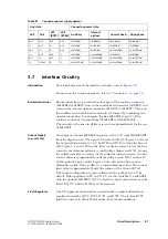
With this option, link LK1 connects
+13
V
8
BATT
of the power connector to
the power-up circuitry. With this option, when a 13.8V supply is connected
to the radio, the radio enters the programmed power-on mode. The
ON
/
OFF
key can then be used to switch the radio on and off. This option has the
disadvantage that the radio still draws about 50mA after being switched off
using the
ON
/
OFF
key. The reason is that the radio enters the stand-by mode
and does not shut down completely.
Auxiliary Power
Sense
(Ignition Sense)
This option uses the digital input line
AUX
GPI
3
of the auxiliary connector to
power the radio up and down. Link LK2 is required to connect the line to
the power-up circuitry. The line is active high; it is on when the level
exceeds 2.6V and off when the level falls below 0.7V; the line tolerates
maximum inputs equal to the radio supply voltage. When the line becomes
active, the radio enters the programmed power-on mode. The
ON
/
OFF
key
can then be used to switch the radio on and off. With the radio off and the
line active, the radio draws about 50mA. When the line becomes inactive,
the radio is shut down completely regardless of whether it was on or in
stand-by mode. With the line inactive the radio draws less than 1mA.
In a vehicle installation this avoids flattening the battery when the ignition
key is off.
Internal-Options
Power Sense
This option is similar to the auxiliary power-sense option, except that the
IOP GPIO
7
line of the internal options connector is used. Link LK4 is required
to connect the line to the power-up circuitry. This line is active high; it is
on when the level exceeds 2.6V and off when the level falls below 0.7V;
the line tolerates maximum inputs of 5V. The behaviour of the
ON
/
OFF
key
is the same as with the auxiliary power-sense option.
No Power Sense
If no power-sense option is selected, the radio can only be powered up and
powered down by means of the
ON
/
OFF
key. For this option, the links LK1,
LK2 and LK4 must be removed. The advantage of this option over the
battery power-sense option is that the radio draws less than 1mA when it is
switched off.
Emergency
Power Sense
This option uses the
AUX
GPI
2
line of the auxiliary connector. Externally, this
line is typically connected to a hidden switch. Internally, link LK3 is
required to connect the line to the power-up circuitry. The line is active low
and has an internal pull-up resistor to the external supply voltage. The line
is on when the level falls below 0.7V. When the line becomes active (when
the hidden switch is pressed for two seconds) the radio enters the emergency
mode. This mode can also be activated by making an emergency call or by
pressing a key that has been programmed appropriately. The concealed
microphone is typically fitted when the emergency power-sense option is
selected.
Содержание TM8235
Страница 1: ...TM8100 mobiles TM8200 mobiles Service Manual MMA 00005 04 Issue 4 June 2006...
Страница 10: ...10 TM8100 TM8200 Service Manual Tait Electronics Limited June 2006...
Страница 62: ...62 Description TM8100 TM8200 Service Manual Tait Electronics Limited June 2006...
Страница 148: ...148 Disassembly and Reassembly TM8100 TM8200 Service Manual Tait Electronics Limited June 2006...
Страница 162: ...162 Servicing Procedures TM8100 TM8200 Service Manual Tait Electronics Limited June 2006...
Страница 178: ...178 Interface Fault Finding TM8100 TM8200 Service Manual Tait Electronics Limited June 2006...
Страница 258: ...258 Receiver Fault Finding TM8100 TM8200 Service Manual Tait Electronics Limited June 2006...
Страница 380: ...380 Transmitter Fault Finding 25W TM8100 TM8200 Service Manual Tait Electronics Limited June 2006...
Страница 404: ...404 CODEC and Audio Fault Finding TM8100 TM8200 Service Manual Tait Electronics Limited June 2006...
Страница 428: ...428 Fault Finding of Control Head with Graphical Display TM8100 TM8200 Service Manual Tait Electronics Limited June 2006...
Страница 446: ...446 Spare Parts TM8100 TM8200 Service Manual Tait Electronics Limited June 2006...
Страница 447: ...TM8100 TM8200 Service Manual 447 Tait Electronics Limited June 2006 TM8100 mobiles TM8200 mobiles Chapter 3 Accessories...
Страница 470: ...470 TMAA01 01 Line Interface Board TM8100 TM8200 Service Manual Tait Electronics Limited June 2006...
Страница 506: ...506 TMAA02 08 Keypad Microphone TM8100 TM8200 Service Manual Tait Electronics Limited June 2006...
Страница 523: ...TM8100 TM8200 Service Manual Installing a Remote Kit 523 Tait Electronics Limited June 2006 Circuit Diagram...
Страница 526: ...526 Installing a Remote Kit TM8100 TM8200 Service Manual Tait Electronics Limited June 2006 Circuit Diagram...
Страница 539: ...TM8100 TM8200 Service Manual Installing an Enhanced Remote Kit 539 Tait Electronics Limited June 2006 Circuit Diagram...
Страница 542: ...542 Installing an Enhanced Remote Kit TM8100 TM8200 Service Manual Tait Electronics Limited June 2006 Circuit Diagram...
Страница 550: ...550 TMAA04 05 Ignition Sense Kit TM8100 TM8200 Service Manual Tait Electronics Limited June 2006...
Страница 554: ...554 TMAA10 01 Desktop Microphone TM8100 TM8200 Service Manual Tait Electronics Limited June 2006...


