TM8100/TM8200 Service Manual
Transmitter Fault Finding (25W)
323
© Tait Electronics Limited
June 2006
12
Transmitter Fault Finding (25W)
Introduction
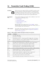
This section covers the diagnosis of faults in the 25W transmitter circuitry.
The main indication of a fault in the transmitter is a reduction in range.
This implies that the power output is wrong or too low. Another type of
fault is manifested when the radio always transmits at full power, even if set
otherwise. Regardless of the fault, the lock status should be normal.
Fault-Diagnosis
Tasks
The procedure for diagnosing transmitter faults is divided into tasks, which
are grouped into the following sections:
■
■
■
“Biasing of PA Driver and PAs”
■
Before beginning the fault diagnosis with
, note the
following information regarding CCTM commands, frequency bands, can
removal and replacement, and transmit tests.
CCTM Commands
The CCTM commands required in this section are listed in
.
Full details of the commands are given in
.
Table 12.1
CCTM commands required for the diagnosis of faults in the transmitter
Command
Description
32
Set radio in receive mode
33
Set radio in transmit mode
47
Read temperature near PAs — displays temperature
x
in degrees celsius and voltage
y
101
x
y
0
Set transmit frequency (
x
in hertz) and receive frequency (
y
in hertz) to specified values
114
x
Set DAC value
x
(in range 0 to 1023) of transmit power
304
Read clamp current at gate of PA driver — displays DAC value
x
(in range 0 to 255)
304
x
Set DAC value
x
(in range 0 to 255) of clamp current at gate of PA driver
318
Read forward-power level — displays corresponding voltage
x
in millivolts
319
Read reverse-power level — displays corresponding voltage
x
in millivolts
326
x
Set transmitter power level
x
(0=off, 1=very low, 2=low, 3=medium, 4=high, 5=maximum)
331
Read bias voltage for first PA — displays DAC value
x
(in range 0 to 255)
331
x
Set DAC value
x
(in range 0 to 255) of bias voltage for first PA
332
Read bias voltage for second PA — displays DAC value
x
(in range 0 to 255)
332
x
Set DAC value
x
(in range 0 to 255) of bias voltage for second PA
334
x
Set synthesizer on (
x
=1) or off (
x
=0) via DIG SYN EN line
335
x
Set transmit-receive switch on (
x
=1) or off (
x
=0) via DIG SYN TR SW line
Содержание TM8235
Страница 1: ...TM8100 mobiles TM8200 mobiles Service Manual MMA 00005 04 Issue 4 June 2006...
Страница 10: ...10 TM8100 TM8200 Service Manual Tait Electronics Limited June 2006...
Страница 62: ...62 Description TM8100 TM8200 Service Manual Tait Electronics Limited June 2006...
Страница 148: ...148 Disassembly and Reassembly TM8100 TM8200 Service Manual Tait Electronics Limited June 2006...
Страница 162: ...162 Servicing Procedures TM8100 TM8200 Service Manual Tait Electronics Limited June 2006...
Страница 178: ...178 Interface Fault Finding TM8100 TM8200 Service Manual Tait Electronics Limited June 2006...
Страница 258: ...258 Receiver Fault Finding TM8100 TM8200 Service Manual Tait Electronics Limited June 2006...
Страница 380: ...380 Transmitter Fault Finding 25W TM8100 TM8200 Service Manual Tait Electronics Limited June 2006...
Страница 404: ...404 CODEC and Audio Fault Finding TM8100 TM8200 Service Manual Tait Electronics Limited June 2006...
Страница 428: ...428 Fault Finding of Control Head with Graphical Display TM8100 TM8200 Service Manual Tait Electronics Limited June 2006...
Страница 446: ...446 Spare Parts TM8100 TM8200 Service Manual Tait Electronics Limited June 2006...
Страница 447: ...TM8100 TM8200 Service Manual 447 Tait Electronics Limited June 2006 TM8100 mobiles TM8200 mobiles Chapter 3 Accessories...
Страница 470: ...470 TMAA01 01 Line Interface Board TM8100 TM8200 Service Manual Tait Electronics Limited June 2006...
Страница 506: ...506 TMAA02 08 Keypad Microphone TM8100 TM8200 Service Manual Tait Electronics Limited June 2006...
Страница 523: ...TM8100 TM8200 Service Manual Installing a Remote Kit 523 Tait Electronics Limited June 2006 Circuit Diagram...
Страница 526: ...526 Installing a Remote Kit TM8100 TM8200 Service Manual Tait Electronics Limited June 2006 Circuit Diagram...
Страница 539: ...TM8100 TM8200 Service Manual Installing an Enhanced Remote Kit 539 Tait Electronics Limited June 2006 Circuit Diagram...
Страница 542: ...542 Installing an Enhanced Remote Kit TM8100 TM8200 Service Manual Tait Electronics Limited June 2006 Circuit Diagram...
Страница 550: ...550 TMAA04 05 Ignition Sense Kit TM8100 TM8200 Service Manual Tait Electronics Limited June 2006...
Страница 554: ...554 TMAA10 01 Desktop Microphone TM8100 TM8200 Service Manual Tait Electronics Limited June 2006...


