414
Fault Finding of Control Head with Graphical Display
TM8100/TM8200 Service Manual
© Tait Electronics Limited
June 2006
14.6
Function Key LEDs or Status LEDs Faulty
The function key LEDs (
F1
and
F4
) and the red, green and amber status
LEDs each are controlled by an FPGA signal and a transistor (Q604 to
Q608). The brightness level is controlled by two FPGA signals, resulting in
four intensity levels (off, low, medium and high).
LED Faulty
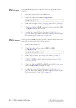
If one of the function key LEDs or status LEDs is faulty:
1.
Send CCTM command
1001 x 1
(where
x
is the LED number:
0=F1, 1=F4, 2=amber, 3=green, 4=red) to activate the relevant
LED.
2.
Check the resistors R34, R35, and R36 in the paths of the green
LEDs.
3.
Measure the voltage at the point between the LED and the transistor.
If the voltage is incorrect, replace the LED.
4.
Replace the corresponding transistor.
LED Intensity Faulty
If the intensity of the LEDs is faulty:
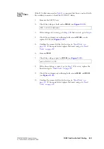
1.
Send CCTM command
1001 0 1
to activate the LED of the
F1
key.
2.
Send CCTM command
1002 3
to set the LED intensity level to high.
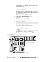
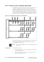
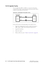
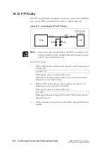
Figure 14.5
Circuit diagram of the function key LEDs and status LEDs
IND BRIGHT1
R601
FPGA
IND BRIGHT2
LED FUNC 1
LED FUNC 4
LED IND TX
LED IND RX
LED IND BUSY
3V3
R602
R603
R604
R34
0
D613
F1 Key
3V3
R605
R35
0
D614
F4 Key
Q604
Q605
3V3
R609
D615
Red
Q606
3V3
R612
R36
0
D616
Green
Q607
3V3
R616
D617
Amber
Q608
R34: 0
Ω
R35: 0
Ω
R36: 0
Ω
D613/Q604 (F1 key LED):
D614/Q605 (F4 key LED):
D615/Q606 (red status LED):
D616/Q607 (green status LED):
D617/Q608 (amber status LED):
1.87V (on)
1.87V (on)
1.92V (on)
1.87V (on)
1.89V (on)
1.40V (off)
1.40V (off)
1.57V (off)
1.40V (off)
1.48V (off)
Содержание TM8235
Страница 1: ...TM8100 mobiles TM8200 mobiles Service Manual MMA 00005 04 Issue 4 June 2006...
Страница 10: ...10 TM8100 TM8200 Service Manual Tait Electronics Limited June 2006...
Страница 62: ...62 Description TM8100 TM8200 Service Manual Tait Electronics Limited June 2006...
Страница 148: ...148 Disassembly and Reassembly TM8100 TM8200 Service Manual Tait Electronics Limited June 2006...
Страница 162: ...162 Servicing Procedures TM8100 TM8200 Service Manual Tait Electronics Limited June 2006...
Страница 178: ...178 Interface Fault Finding TM8100 TM8200 Service Manual Tait Electronics Limited June 2006...
Страница 258: ...258 Receiver Fault Finding TM8100 TM8200 Service Manual Tait Electronics Limited June 2006...
Страница 380: ...380 Transmitter Fault Finding 25W TM8100 TM8200 Service Manual Tait Electronics Limited June 2006...
Страница 404: ...404 CODEC and Audio Fault Finding TM8100 TM8200 Service Manual Tait Electronics Limited June 2006...
Страница 428: ...428 Fault Finding of Control Head with Graphical Display TM8100 TM8200 Service Manual Tait Electronics Limited June 2006...
Страница 446: ...446 Spare Parts TM8100 TM8200 Service Manual Tait Electronics Limited June 2006...
Страница 447: ...TM8100 TM8200 Service Manual 447 Tait Electronics Limited June 2006 TM8100 mobiles TM8200 mobiles Chapter 3 Accessories...
Страница 470: ...470 TMAA01 01 Line Interface Board TM8100 TM8200 Service Manual Tait Electronics Limited June 2006...
Страница 506: ...506 TMAA02 08 Keypad Microphone TM8100 TM8200 Service Manual Tait Electronics Limited June 2006...
Страница 523: ...TM8100 TM8200 Service Manual Installing a Remote Kit 523 Tait Electronics Limited June 2006 Circuit Diagram...
Страница 526: ...526 Installing a Remote Kit TM8100 TM8200 Service Manual Tait Electronics Limited June 2006 Circuit Diagram...
Страница 539: ...TM8100 TM8200 Service Manual Installing an Enhanced Remote Kit 539 Tait Electronics Limited June 2006 Circuit Diagram...
Страница 542: ...542 Installing an Enhanced Remote Kit TM8100 TM8200 Service Manual Tait Electronics Limited June 2006 Circuit Diagram...
Страница 550: ...550 TMAA04 05 Ignition Sense Kit TM8100 TM8200 Service Manual Tait Electronics Limited June 2006...
Страница 554: ...554 TMAA10 01 Desktop Microphone TM8100 TM8200 Service Manual Tait Electronics Limited June 2006...

