TM8100/TM8200 Service Manual
Circuit Descriptions
75
© Tait Electronics Limited
June 2006
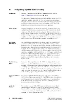
Active Loop Filter
The loop filter continuously integrates the current pulses from the charge
pump and produces a steady DC output voltage that tunes the VCO
(or VCOs). When the VCO frequency is correct, there is no frequency
error and therefore no charge-pump output, and so the loop filter’s output
voltage remains constant. If the frequency is too high or too low, the error
will result in the output of charge-pump current pulses (negative or positive
depending on the sign of the error). The loop filter’s output voltage will
change accordingly, causing the VCO frequency to change in proportion.
The synthesizer design is such that normally the VCO frequency will be
automatically corrected.
Re-tuning of VCO
Frequency
When the radio changes channels or switches between receive and transmit,
the VCO frequency must be changed. The rate at which the VCO is re-
tuned is dependent on many factors, of which the loop filter is the main
factor. The loop filter is an integrator built around an operational amplifier.
The resistors and capacitors of the filter affect both the switching time and
the stability of the synthesizer; the values of these components have been
carefully selected to give optimum control characteristics.
Speed-up
Techniques
To reduce the change-over time between transmit and receive, part-time
speed-up techniques have been implemented. Speed-up involves changing
some resistor values while simultaneously changing the PLL IC settings.
This process is implemented in hardware under software control in
conjunction with use of the synthesized reference input. The result is a
transmit-receive settling time of less than 4.5ms. (The switching time is
measured for a frequency change equal to the first IF plus 10MHz or 1MHz,
depending on the repeater offsets used for the band. This implies a
synthesizer transmit-receive change-over plus an offset of 1MHz or 10MHz
in less than 4.5ms. The ramp-up and ramp-down of the transmitter, which
totals 1ms, extends this change-over time to 5.5ms.)
Содержание TM8235
Страница 1: ...TM8100 mobiles TM8200 mobiles Service Manual MMA 00005 04 Issue 4 June 2006...
Страница 10: ...10 TM8100 TM8200 Service Manual Tait Electronics Limited June 2006...
Страница 62: ...62 Description TM8100 TM8200 Service Manual Tait Electronics Limited June 2006...
Страница 148: ...148 Disassembly and Reassembly TM8100 TM8200 Service Manual Tait Electronics Limited June 2006...
Страница 162: ...162 Servicing Procedures TM8100 TM8200 Service Manual Tait Electronics Limited June 2006...
Страница 178: ...178 Interface Fault Finding TM8100 TM8200 Service Manual Tait Electronics Limited June 2006...
Страница 258: ...258 Receiver Fault Finding TM8100 TM8200 Service Manual Tait Electronics Limited June 2006...
Страница 380: ...380 Transmitter Fault Finding 25W TM8100 TM8200 Service Manual Tait Electronics Limited June 2006...
Страница 404: ...404 CODEC and Audio Fault Finding TM8100 TM8200 Service Manual Tait Electronics Limited June 2006...
Страница 428: ...428 Fault Finding of Control Head with Graphical Display TM8100 TM8200 Service Manual Tait Electronics Limited June 2006...
Страница 446: ...446 Spare Parts TM8100 TM8200 Service Manual Tait Electronics Limited June 2006...
Страница 447: ...TM8100 TM8200 Service Manual 447 Tait Electronics Limited June 2006 TM8100 mobiles TM8200 mobiles Chapter 3 Accessories...
Страница 470: ...470 TMAA01 01 Line Interface Board TM8100 TM8200 Service Manual Tait Electronics Limited June 2006...
Страница 506: ...506 TMAA02 08 Keypad Microphone TM8100 TM8200 Service Manual Tait Electronics Limited June 2006...
Страница 523: ...TM8100 TM8200 Service Manual Installing a Remote Kit 523 Tait Electronics Limited June 2006 Circuit Diagram...
Страница 526: ...526 Installing a Remote Kit TM8100 TM8200 Service Manual Tait Electronics Limited June 2006 Circuit Diagram...
Страница 539: ...TM8100 TM8200 Service Manual Installing an Enhanced Remote Kit 539 Tait Electronics Limited June 2006 Circuit Diagram...
Страница 542: ...542 Installing an Enhanced Remote Kit TM8100 TM8200 Service Manual Tait Electronics Limited June 2006 Circuit Diagram...
Страница 550: ...550 TMAA04 05 Ignition Sense Kit TM8100 TM8200 Service Manual Tait Electronics Limited June 2006...
Страница 554: ...554 TMAA10 01 Desktop Microphone TM8100 TM8200 Service Manual Tait Electronics Limited June 2006...


