TM8100/TM8200 Service Manual
Transmitter Fault Finding (40W/50W)
261
© Tait Electronics Limited
June 2006
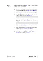
Transmit Tests
The following actions need to be taken when carrying out transmit tests:
■
secure the board
■
ensure the proper antenna load
■
limit the duration of transmit tests
■
protect against accidental transmissions
■
avoid thermal and RF burns.
These points are discussed in more detail in the following sections.
Secure the Board
Before conducting any transmit tests, ensure that the board is adequately
secured in the chassis. This is essential if overheating of the radio is to be
avoided. (As mentioned earlier, the heat-transfer block must already be
secured to the main board of the assembly.) It is good practice to secure the
assembly by at least the two external screws and one of the internal screws.
The screws are labelled
. There is no
need, however, to secure the lid of the radio body.
Ensure Proper
Antenna Load
The radio has been designed to operate with a 50
Ω
termination impedance,
but will tolerate a wide range of antenna loading conditions. Nevertheless,
care should be exercised. Normally the RF connector on the board will be
connected to the RF communications test set as shown in
. But for those tests where this connection is not necessary, a 50
Ω
load may be used instead. Do not operate the transmitter without such a load
or without a connection to the test set. Failure to do so may result in damage
to the power output stage of the transmitter.
Limit Duration of
Transmit Tests
After setting the frequency and power level (if necessary), enter the CCTM
command
33
to perform a transmit test. This command places the radio in
transmit mode. After completing the measurement or check required,
immediately enter the CCTM command
32
. This command returns the
radio to the receive mode. Restricting the duration of transmit tests in this
way will further limit the danger of overheating. The reason for this
precaution is that the transmit timers do not function in the CCTM mode.
Protect Against
Accidental
Transmissions
Under certain circumstances the microprocessor can key on the transmitter.
Ensure that all instruments are protected at all times from such accidental
transmissions.
Avoid Thermal
and RF Burns
Avoid thermal burns. Do not touch the cooling fins or underside of the
radio body when the transmitter is or has been operating. Avoid RF burns.
Do not touch the antenna or the RF signal path on the circuit board while
the transmitter is operating.
Содержание TM8235
Страница 1: ...TM8100 mobiles TM8200 mobiles Service Manual MMA 00005 04 Issue 4 June 2006...
Страница 10: ...10 TM8100 TM8200 Service Manual Tait Electronics Limited June 2006...
Страница 62: ...62 Description TM8100 TM8200 Service Manual Tait Electronics Limited June 2006...
Страница 148: ...148 Disassembly and Reassembly TM8100 TM8200 Service Manual Tait Electronics Limited June 2006...
Страница 162: ...162 Servicing Procedures TM8100 TM8200 Service Manual Tait Electronics Limited June 2006...
Страница 178: ...178 Interface Fault Finding TM8100 TM8200 Service Manual Tait Electronics Limited June 2006...
Страница 258: ...258 Receiver Fault Finding TM8100 TM8200 Service Manual Tait Electronics Limited June 2006...
Страница 380: ...380 Transmitter Fault Finding 25W TM8100 TM8200 Service Manual Tait Electronics Limited June 2006...
Страница 404: ...404 CODEC and Audio Fault Finding TM8100 TM8200 Service Manual Tait Electronics Limited June 2006...
Страница 428: ...428 Fault Finding of Control Head with Graphical Display TM8100 TM8200 Service Manual Tait Electronics Limited June 2006...
Страница 446: ...446 Spare Parts TM8100 TM8200 Service Manual Tait Electronics Limited June 2006...
Страница 447: ...TM8100 TM8200 Service Manual 447 Tait Electronics Limited June 2006 TM8100 mobiles TM8200 mobiles Chapter 3 Accessories...
Страница 470: ...470 TMAA01 01 Line Interface Board TM8100 TM8200 Service Manual Tait Electronics Limited June 2006...
Страница 506: ...506 TMAA02 08 Keypad Microphone TM8100 TM8200 Service Manual Tait Electronics Limited June 2006...
Страница 523: ...TM8100 TM8200 Service Manual Installing a Remote Kit 523 Tait Electronics Limited June 2006 Circuit Diagram...
Страница 526: ...526 Installing a Remote Kit TM8100 TM8200 Service Manual Tait Electronics Limited June 2006 Circuit Diagram...
Страница 539: ...TM8100 TM8200 Service Manual Installing an Enhanced Remote Kit 539 Tait Electronics Limited June 2006 Circuit Diagram...
Страница 542: ...542 Installing an Enhanced Remote Kit TM8100 TM8200 Service Manual Tait Electronics Limited June 2006 Circuit Diagram...
Страница 550: ...550 TMAA04 05 Ignition Sense Kit TM8100 TM8200 Service Manual Tait Electronics Limited June 2006...
Страница 554: ...554 TMAA10 01 Desktop Microphone TM8100 TM8200 Service Manual Tait Electronics Limited June 2006...

