182
Frequency Synthesizer Fault Finding
TM8100/TM8200 Service Manual
© Tait Electronics Limited
June 2006
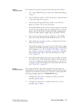
6.
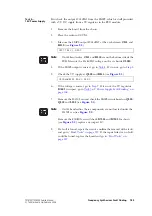
Enter the CCTM command
205
to reset the calibration values to the
default values. Then enter the CCTM command
302 0 10
again to
calibrate the transmit VCO.
7.
If the calibration succeeded, confirm the removal of the fault, and go
to
. If the calibration failed, go to
(UHF radios) or
8.
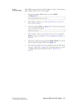
Program the radio with the maximum frequency in the radio’s
frequency band: Enter the CCTM command
101
x x
0
, where
x
is the
frequency in hertz.
9.
Enter the CCTM command
72
to determine the lock status in receive
mode. Note the response.
10.
If the lock status is
111
or
110
, the synthesizer is functioning in the
receive mode, and the power supplies and PLL are functioning
correctly. Go to
to check the loop filter,
VCOs, and buffer amplifiers. If the lock status is
011
or
010
, the
synthesizer is faulty in the receive mode. Go to
Task 2 —
Lock Status
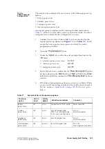
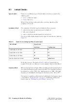
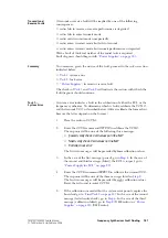
A lock error indicates that the frequency synthesizer, FCL or second LO is
out of lock. To determine which is faulty, check the lock status as described
below.
1.
If not already done, place the radio in CCTM.
2.
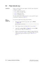
Program the radio with the receive frequency of a channel that is
known to be out of lock: Enter the CCTM command
101
x x
0
,
where
x
is the frequency in hertz.
3.
Enter the CCTM command
72
to determine the lock status in receive
mode. Note the response. The action required depends on the lock
status as described in the following steps.
4.
If the lock status is
x
0
x
, where
x
is
0
or
1
, the FCL is suspect; go to
“Power Supply for FCL” on page 227
5.
If the lock status is
011
, the synthesizer is suspect, although the power
supplies are functioning correctly; go to
6.
If the lock status is
010
, the synthesizer and second LO are both out
of lock. First investigate the synthesizer, excluding the power supplies;
go to
. If necessary, investigate the receiver
later.
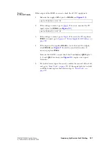
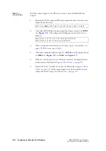
lock status=
xyz
(
x
=RF PLL;
y
=FCL;
z
=LO2) (0=not in lock; 1=in lock)
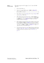
lock status=
xyz
(
x
=RF PLL;
y
=FCL;
z
=LO2) (0=not in lock; 1=in lock)
Содержание TM8235
Страница 1: ...TM8100 mobiles TM8200 mobiles Service Manual MMA 00005 04 Issue 4 June 2006...
Страница 10: ...10 TM8100 TM8200 Service Manual Tait Electronics Limited June 2006...
Страница 62: ...62 Description TM8100 TM8200 Service Manual Tait Electronics Limited June 2006...
Страница 148: ...148 Disassembly and Reassembly TM8100 TM8200 Service Manual Tait Electronics Limited June 2006...
Страница 162: ...162 Servicing Procedures TM8100 TM8200 Service Manual Tait Electronics Limited June 2006...
Страница 178: ...178 Interface Fault Finding TM8100 TM8200 Service Manual Tait Electronics Limited June 2006...
Страница 258: ...258 Receiver Fault Finding TM8100 TM8200 Service Manual Tait Electronics Limited June 2006...
Страница 380: ...380 Transmitter Fault Finding 25W TM8100 TM8200 Service Manual Tait Electronics Limited June 2006...
Страница 404: ...404 CODEC and Audio Fault Finding TM8100 TM8200 Service Manual Tait Electronics Limited June 2006...
Страница 428: ...428 Fault Finding of Control Head with Graphical Display TM8100 TM8200 Service Manual Tait Electronics Limited June 2006...
Страница 446: ...446 Spare Parts TM8100 TM8200 Service Manual Tait Electronics Limited June 2006...
Страница 447: ...TM8100 TM8200 Service Manual 447 Tait Electronics Limited June 2006 TM8100 mobiles TM8200 mobiles Chapter 3 Accessories...
Страница 470: ...470 TMAA01 01 Line Interface Board TM8100 TM8200 Service Manual Tait Electronics Limited June 2006...
Страница 506: ...506 TMAA02 08 Keypad Microphone TM8100 TM8200 Service Manual Tait Electronics Limited June 2006...
Страница 523: ...TM8100 TM8200 Service Manual Installing a Remote Kit 523 Tait Electronics Limited June 2006 Circuit Diagram...
Страница 526: ...526 Installing a Remote Kit TM8100 TM8200 Service Manual Tait Electronics Limited June 2006 Circuit Diagram...
Страница 539: ...TM8100 TM8200 Service Manual Installing an Enhanced Remote Kit 539 Tait Electronics Limited June 2006 Circuit Diagram...
Страница 542: ...542 Installing an Enhanced Remote Kit TM8100 TM8200 Service Manual Tait Electronics Limited June 2006 Circuit Diagram...
Страница 550: ...550 TMAA04 05 Ignition Sense Kit TM8100 TM8200 Service Manual Tait Electronics Limited June 2006...
Страница 554: ...554 TMAA10 01 Desktop Microphone TM8100 TM8200 Service Manual Tait Electronics Limited June 2006...

