TM8100/TM8200 Service Manual
Circuit Descriptions
81
© Tait Electronics Limited
June 2006
3.6
Power Supply Circuitry
Introduction
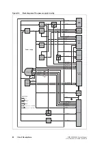
For a block diagram of the power supply circuitry, refer to
The power-supply circuitry consists of the following main sections:
■
supply protection
■
supervisory circuit
■
internal power supplies
■
control of internal power supplies
■
control of external power supply.
Supply Protection
Electrical protection to the radio is provided by the clamping diode D600
and by 20A fuses (for the 40W/50W radios) and 10A fuses (for the 25W
radios) in the positive and negative leads of the power cable. This provides
protection from reverse voltages, positive transients greater than 30V, and all
negative transients. An ADC monitors the supply and is responsible for the
protection of internal devices, which have an operating voltage of less than
30V. The ADC also ensures protection if the radio operates outside its
specified voltage range of 10.8V to 16V.
Supervisory Circuit
The supervisory circuit comprises a reset and watchdog timer. The circuit
provides the reset signal
PSU
SYS
RST
to the digital section, which in turn
provides the watchdog signal
DIG
WD
KICK
required by the supervisory circuit.
Internal Power
Supplies
There are eight internal power supplies:
■
one SMPS (
+3
V
3
)
■
four linear regulators (
+9
V
0
,
+6
V
0
,
+3
V
0
AN
,
+2
V
5
CDC
)
■
three switched supplies (
+9
V
0
TX
,
+3
V
0
RX
,
+13
V
8
SW
).
The SMPS is used to regulate to 3.3V from the external supply
+13
V
8
BATT
.
The four lower voltages required are then further stepped down with linear
regulators. These all take advantage of the efficiency gain of the SMPS.
The 9V regulator and the 13.8V switched supply are connected to
+13
V
8
BATT
. The two remaining switched supplies (9V and 3V) use P-channel
MOSFETs.
Control of Internal
Power Supplies
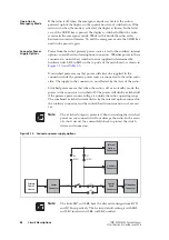
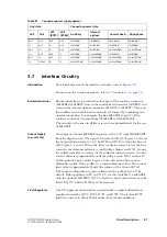
The radio can be switched on using the
ON
/
OFF
key on the control head or
by means of external signals. For the latter case hardware links are required
and there are several power-sense options; these are discussed below. Some
internal power supplies can be controlled by means of digital lines
depending on the mode in which the radio is operating.
Содержание TM8235
Страница 1: ...TM8100 mobiles TM8200 mobiles Service Manual MMA 00005 04 Issue 4 June 2006...
Страница 10: ...10 TM8100 TM8200 Service Manual Tait Electronics Limited June 2006...
Страница 62: ...62 Description TM8100 TM8200 Service Manual Tait Electronics Limited June 2006...
Страница 148: ...148 Disassembly and Reassembly TM8100 TM8200 Service Manual Tait Electronics Limited June 2006...
Страница 162: ...162 Servicing Procedures TM8100 TM8200 Service Manual Tait Electronics Limited June 2006...
Страница 178: ...178 Interface Fault Finding TM8100 TM8200 Service Manual Tait Electronics Limited June 2006...
Страница 258: ...258 Receiver Fault Finding TM8100 TM8200 Service Manual Tait Electronics Limited June 2006...
Страница 380: ...380 Transmitter Fault Finding 25W TM8100 TM8200 Service Manual Tait Electronics Limited June 2006...
Страница 404: ...404 CODEC and Audio Fault Finding TM8100 TM8200 Service Manual Tait Electronics Limited June 2006...
Страница 428: ...428 Fault Finding of Control Head with Graphical Display TM8100 TM8200 Service Manual Tait Electronics Limited June 2006...
Страница 446: ...446 Spare Parts TM8100 TM8200 Service Manual Tait Electronics Limited June 2006...
Страница 447: ...TM8100 TM8200 Service Manual 447 Tait Electronics Limited June 2006 TM8100 mobiles TM8200 mobiles Chapter 3 Accessories...
Страница 470: ...470 TMAA01 01 Line Interface Board TM8100 TM8200 Service Manual Tait Electronics Limited June 2006...
Страница 506: ...506 TMAA02 08 Keypad Microphone TM8100 TM8200 Service Manual Tait Electronics Limited June 2006...
Страница 523: ...TM8100 TM8200 Service Manual Installing a Remote Kit 523 Tait Electronics Limited June 2006 Circuit Diagram...
Страница 526: ...526 Installing a Remote Kit TM8100 TM8200 Service Manual Tait Electronics Limited June 2006 Circuit Diagram...
Страница 539: ...TM8100 TM8200 Service Manual Installing an Enhanced Remote Kit 539 Tait Electronics Limited June 2006 Circuit Diagram...
Страница 542: ...542 Installing an Enhanced Remote Kit TM8100 TM8200 Service Manual Tait Electronics Limited June 2006 Circuit Diagram...
Страница 550: ...550 TMAA04 05 Ignition Sense Kit TM8100 TM8200 Service Manual Tait Electronics Limited June 2006...
Страница 554: ...554 TMAA10 01 Desktop Microphone TM8100 TM8200 Service Manual Tait Electronics Limited June 2006...


