STULZ CyberRow DX Series Installation, Operation & Maintenance Manual
2.7 Water- Water/Glycol Cooled DX
(CRS-W & CRS-G Models)
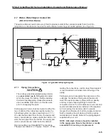
The system utilizes an external source of fl uid to provide coolant to the condenser inside the A/C unit. No
refrigeration connections are required for self-contained water or glycol cooled systems (see Figure 4).
TEMPERATURE
SENSOR
T
COMPRESSOR
CONNECTIONS
CONDENSER WATER
IN
WATER REGULATING
VALVE
OUT
OPTIONAL PIPING
CONNECTION
SWITCH LIMIT
SCHRADER
HIGH PRESSURE
HP
VALVE
WATER COOLED CONDENSER
DRIER/STRAINER
REFRIGERANT
LP
SCHRADER
VALVE
LIMIT SWITCH
LOW PRESSURE
DISTRIBUTOR BODY
EVAPORATOR COIL
PT
PRESSURE
TRANSDUCER
THERMAL
EXPANSION
VALVE
PT
PRESSURE
TRANSDUCER
REGULATOR
HOT GAS
ASC
ELECTRONIC
SIGHT
GLASS
Figure 4- Typical W/G Piping Diagram
2.7.1 Piping Connections
CAUTION
The cooling coil (and associated piping circuits)
are
pressurized (up to 100 psi)
and sealed
when they leave the factory. Before installing
the interconnecting piping, release the pressure
via an available stem valve or schrader valve
prior to uncapping the pipes.
Fluid supply and return lines are routed to either the
top or bottom of the cabinet as specifi ed when the
CyberRow system is ordered (see Section 2.7.1.1).
On units that are piped from the top, the supply and
return connections are made outside the cabinet. On
units that are piped from the bottom, the supply and
return connections are made inside the cabinet.
Pipe connections are threaded NPT connections.
The pipes are labeled; i.e. “Supply”, “Return”. When
making the connections, a tefl on tape thread sealant
is recommended to minimize internal fouling of the
piping.
Field piping is not necessarily the same size as the
units pipe connections. Piping should be sized to
match the system pressure drop and fl ow capacity,
and may require reducing fi ttings to match the
connection size on the air conditioner. An air vent and
several schrader valves are installed in the precision
A/C unit piping. It is recommended to provide
manual shut-off valves for both the supply and return
fl uid for isolating the unit when performing routine
maintenance or repairs. Refer to the piping diagram
supplied with your unit.
NOTE: A 60-mesh strainer should be installed
in the supply pipe. Ensure the strainer is readily
accessible for servicing or replacement.
2-5
Содержание CyberRow DX CRS-042-G
Страница 94: ......


