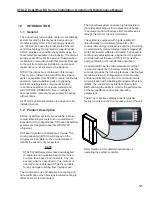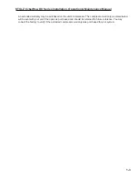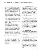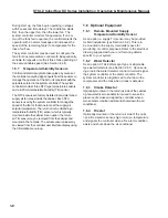
STULZ CyberRow DX Series Installation, Operation & Maintenance Manual
Cable type water detector-
Lay the cable water detector fl at across the sub-fl oor
where water could collect.
Secure the cable every
12-18 inches with J-clips
or cable ties with adhesive
mounting pads when
installing it in the airstream. Secure it at each turn of
the cable and when routing it around obstructions. Do
not tie the water detector cable to a metal fl oor stand
or to pipes.
When a water leak on the fl oor reaches the cable,
current will fl ow between the cable wires. A two
conductor wire harness is provided with a quick
connect fi tting on the end. The harness mates to
the fi tting on the water detector and connects it to
the control terminal block inside the electric box as
shown in the wiring diagram provided with your unit.
2.6.2 Remote Temperature/Humidity Sensor
Depending on the type of control selected, the
temperature/humidity (T/H) sensor may be factory
mounted or shipped loose for fi eld installation. The
remote sensor must be located so that it will prop-
erly sense the temperature/humidity conditions to be
controlled. The T/H sensor should not be mounted
near a doorway or an area where it would be exposed
to direct sunlight. When locating the sensor, consider
the length of wire to be used. The sensor is typically
provided with a 20 foot long cable. As an option, a 75
foot or 150 foot long cable may be provided. Follow
the steps below to mount the sensor.
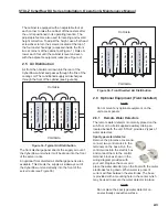
Temperature /Humidity Sensor
1.
Remove the cover from the base of the sensor by
squeezing it at the top and bottom.
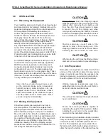
CAUTION
Take care not to damage the exposed tem-
perature/humidity sensors on the PC board
when the cover is removed. The sensors can
be damaged if handled improperly.
2.
Place the base temporarily against the mounting
surface.
3.
Level the base. Mark and drill mounting holes
through at least two of the available slotted holes.
4.
Run the 3 conductor shielded cable through the
opening in the base, then secure the base with
screws ensuring the word TOP on the PC board
is oriented upward.
5.
Make the wiring connections. Refer to Section
2.9, Utility Connections and refer to the wiring
diagram supplied with your unit.
6.
Seal the hole in the wall behind the sensor.
7.
Replace the cover plate on the base.
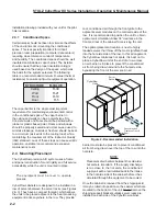
CAUTION
The sensor can be damaged if handled
improperly. Take care not to damage the
exposed temperature/humidity sensor on the
PC board. Do not touch the sensor as this will
affect its accuracy.
2.6.3 Outdoor Condensers
Referring to the IOM manual provided with the
condenser, install the remote condenser in a secure
location where it cannot be tampered with and the
service disconnect switch cannot be inadvertently
turned off. Locate the remote condenser where the
fan is not likely to draw dirt and debris into the coil
fi ns. The clearance around the condenser should
be at least 1x the units width to ensure adequate
airfl ow to the coil. Secure the condenser to prevent
the system from moving during operation. It is
recommended that the remote condenser be installed
with vibration mounts to reduce vibration transmitted
to the mounting surface.
2-4
Содержание CyberRow DX CRS-042-G
Страница 94: ......


