background image

STULZ CyberRow DX Series Installation, Operation & Maintenance Manual

4-33

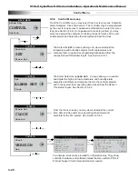
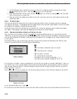
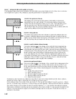
PLAN ADDRESS: 

1


UP:    INCREASE

DOWN:  DECREASE

ENTER: SAVE & EXIT

Controller Address Confi guration

P:02 Adr  Priv/Shared
Trm1 

31

Pr

Trm2 

None


--

Trm3 

None


--

 Ok?

No

Terminal Confi guration

The Display Address Changed screen will appear indicating 
the display address selected is not the same as the one saved 
previously and the new value will be saved to the permanent 
memory. 

3. Once the terminal address is set to zero, cycle the power to the
unit Off and then back On.

NOTE:

 If the “

Display address setting:__

" fi eld is set to 

0

, the terminal will communicate with the controller 

(I/O board) using point-to-point protocol (not pLAN). The display fi eld “

I/O Board address:__

” will disappear as it 

has no meaning until you set the controller (I/O board) pLAN address. 

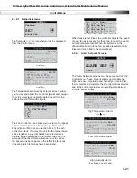
4.6.2.2 Confi gure the Controller (I/O Board) pLAN Address 

Immediately after turning power back on, press and hold the Alarm ( ) and the Up ( ) Arrow keys simultaneously for 10 
to 15 seconds. First you will see a display message “

self test please wait

” then the pLAN Address Confi guration 

screen shown below will appear.  

Don’t press the (

) key, the cursor is already in the modifi able fi eld.

Press the ( ) key to set the pLAN address (#1 – 8) for the controller 
(I/O Board). The pLAN address #1 is already assigned by default 
to the fi rst (Lead) controller in the group. Address #2 is to be 
assigned to the fi rst controller added to the group (address #3 is to 

be assigned to the second controller added and so on). Then press 
the (

) key to confi rm your selection. A message “

NO LINK

” will 

appear.

Next , press the Up ( ), Down


( ) and Enter (

) keys simultaneously. Reconfi gure the terminal address following 

the steps in Section 4.6.2 again. This time set the terminal address to match the corresponding controller (I/O board) 
address.. If the controller is assigned address 2, then the corresponding terminal address should be set to 31 as 
shown in the table on the preceding page. If the next controller is assigned address 3, the corresponding terminal 
should be set to 30. 

After setting the correct terminal address, press the (

) key once to confi rm your selection. A message “

NO LINK

” 

will appear. At this point, the terminal has been set with the correct address for the controller and the controller has 
been set for the terminal, but now they need to be assigned to each other.

4.6.2.3 

Assign the Terminal to the Controller

1. Access the Terminal Address Confi guration screen again using the Up ( ), Down ( ) and Enter (

) keys.

2. Press the (

) key until the cursor moves to the fi eld “

I/O board address:__

”.

3. Using the ( ) ( ) keys, enter the address (1 – 8) for the controller I/O board.

4. Press the (

) key twice to display the Terminal Confi guration screen shown below.

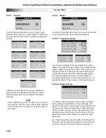
5. Here too, the (

) key moves the cursor from one fi eld to the next,

and the ( ) ( ) keys change the value of the current fi eld. The fi eld

P:0_

” depicts the pLAN address (1 – 8) assigned to the I/O board. In

the example shown, the controller has been assigned address 2.

6. Press the (

) key to move to the fi eld “

Trm1 xx

”.  The fi eld

represents the address of the terminal associated with the controller.
Using the ( ) ( ) keys enter the address (25 – 32) of the terminal
assigned to the controller (I/O board). In the example shown, address
31 has been entered for the fi rst A/C unit added to the group.

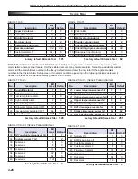
Display address 
changed

  Display Address Changed

Содержание CyberRow DX CRS-042-G

Страница 1: ...CyberRow DX Installation Operation and Maintenance Manual Row Based Precision Air Conditioners 12 kW 33 kW 60 Hz...

Страница 2: ...ystems Inc STULZ This document contains confidential and proprietary information of STULZ Air Technology Systems Inc Distributing or photocopying this document for external distribution is in direct v...

Страница 3: ...2 9 Utility Connections 2 10 2 9 1 Main Power 2 10 2 9 2 Optional Equipment 2 11 TABLE OF CONTENTS 2 9 2 1 Remote Water Detector 2 11 2 9 2 2 Remote Temperature Humidity Sensor 2 11 2 9 2 3 Remote On...

Страница 4: ...tion 2 3 Figure 4 Typical W G Piping Diagram 2 5 Figure 5 Typical RemoteAir Cooled DX Piping Diagram 2 7 Figure 6 Sample Nameplate 2 10 Figure 7 Field Wiring Glycol Systems 2 12 Figure 8 Field Wiring...

Страница 5: ...dentify the capacity of your system NOTE STULZ CyberRow systems have been designed to capture and neutralize heat within close coupled rack based environments Any use beyond what is described in this...

Страница 6: ...STULZ CyberRow DX Series Installation Operation Maintenance Manual 1 2 1 3 Product Warranty See the contract...

Страница 7: ...nty may be purchased on the unit s compressor The compressor warranty as stated below will be sent with your unit if the option is purchased and should be retained for future reference You may consult...

Страница 8: ...an air conditioning technician CAUTION When moving the unit it must be kept in its normal installed position If the unit is not kept level and vertical damage to the compressors will result WARNING N...

Страница 9: ...all for the use and handling of chemicals solvents or cleansers Always refer to the manufacturer s Material Safety Data Sheet MSDS prior to using these materials Clean parts in a well ventilated area...

Страница 10: ...n some cases an addendum to this manual may also be included to further describe the feature s Figure 1 depicts a typical internal layout and identifies the major components of a typical CyberRow unit...

Страница 11: ...ering the evaporator to maintain the correct superheat temperature 1 5 3 2 Electronic Hot Gas Bypass Used for freeze protection and capacity control an electronically controlled hot gas bypass valve i...

Страница 12: ...onitored by a temperature humidity T H sensor which is typically mounted inside the cabinet As an option the return air T H sensor may be removed from the cabinet and mounted in the hot aisle The actu...

Страница 13: ...olted to the skid to facilitate moving the unit prior to installation Move the unit on the skid with a suitable device such as a forklift pallet jack or roller bar and dollies which are capable of han...

Страница 14: ...while the unit is mounted in place NOTE The equipment must be level to operate properly CyberRow cabinets are designed to be installed in a row of servers between the server racks see Figures 2 3 They...

Страница 15: ...server racks An optional front diverted air discharge panel is also available This directs the supply air sideways out of the CyberRow unit and directly into the front of the server racks see Figure...

Страница 16: ...ure Humidity Sensor 1 Remove the cover from the base of the sensor by squeezing it at the top and bottom CAUTION Take care not to damage the exposed tem perature humidity sensors on the PC board when...

Страница 17: ...ping the pipes Fluid supply and return lines are routed to either the top or bottom of the cabinet as specified when the CyberRow system is ordered see Section 2 7 1 1 On units that are piped from the...

Страница 18: ...lled seal the gaps between the pipes and the entrance holes so air won t leak around the pipes NOTE Water Glycol lines should be insulated to prevent condensation from forming on the pipes if ambient...

Страница 19: ...A C unit are routed to either the top or bottom of the cabinet as specified when the CyberRow system is ordered see Section 2 8 1 1 The connections are made inside the cabinet The pipe stubs are labe...

Страница 20: ...h Tee has an equivalent length of 3 5 feet These corrections must be accounted for when sizing your piping debris to get inside refrigerant lines Dry nitrogen should be flowing through the tubing whil...

Страница 21: ...risers double rises may be necessary CAUTION Do not exceed 150 ft maximum Liquid Line length If the condenser is installed above the evaporator the discharge line should include a p trap at the lowest...

Страница 22: ...s may become loose during transit of the equip ment therefore it is required to verify that all wiring terminations are secure WARNING Verify power is turned off before making con nections to the equi...

Страница 23: ...ical drawing supplied with your unit to determine the total number of interconnecting conductors required for your system NOTE All wiring must be provided in accordance with local and national electri...

Страница 24: ...ng Field Wiring Glycol Systems 1 PHANTOM WIRES NOT APPLICABLE FOR SINGLE PHASE POWER SUPPLIES NOTES TO BE INSTALLED IN ACCORDANCE GLYCOL UNITS ONLY ELECTRIC 24VAC PUMP PACKAGE BOX SEE NOTE 1 WITH NFPA...

Страница 25: ...compressor is running You must remove the jumper from the remote condenser terminal board see the condenser wiring diagram Wire 24 VAC control conductors from the terminal board within the A C unit to...

Страница 26: ...VE oil is used in systems with R410A refrigerant PVE oil quickly absorbs moisture when exposed to air High PVE oil moisture levels react with refrigerant to form acid which results in system contamina...

Страница 27: ...oisture prior to charging If this is not done the refrigerant charge will combine with moisture in the pipes to form an acid that will eventually lead to compressor failure A triple evacuation procedu...

Страница 28: ...id form rather than vapor form Cylinders which are not provided with dip tubes should be inverted to allow only liquid refrigerant to charge the system Keeping the temperature of the cylinder below 85...

Страница 29: ...ranty Registration and Start Up Checklist 2 10 2 4 30 F Ambient Applications NOTE For units designed for 30 F operation a receiver is used to store the refrigerant during the time the condenser is not...

Страница 30: ...nges the control valve position to maintain head pressure based on the difference between the setpoint value and the actual measured value The controller transmits a proportional 0 to 10 VDC signal to...

Страница 31: ...tor through an auxiliary connection downstream of the thermal expansion valve This is used to maintain the evaporator at a minimum constant pressure as the heating load varies The hot gas discharge re...

Страница 32: ...llowed after the first fan turns on before the controller polls the air proving switch If adequate air flow is detected the controller enables its outputs If the actual room conditions are not within...

Страница 33: ...efault setpoints The primary setpoints entered by the factory still remain stored in the controllers memory as Factory setpoints The setpoints for the system may be re adjusted in the Control menu at...

Страница 34: ...l alphanumeric display equipped with LED illuminated function keys The screens that appear on the user interface display panel present data that originates from the controller I O module Figure 10 The...

Страница 35: ...em numbers that follow coincide with the call outs in Figure 11 1 Connection J10 for interface display panel 2 Connection for pLAN J11 3 Hatch for BMS or network card 4 Power on LED Yellow 5 Signal LE...

Страница 36: ...may be protected by a built in security protocol and may require the use of a password to gain access Figure 13 Menu Selections 4 2 2 Menus From the Main screen you may press the Program Prg key to s...

Страница 37: ...of the Enter key will advance the cursor through the various modifiable fields of the display screen eventually returning to the first field Values that are already correct may simply be skipped over...

Страница 38: ...ss will be allowed If the entered password authority level is lower than the level requested the words WRONG PASSWORD will appear for several seconds at the bottom of the screen 4 2 6 2 Wrong Password...

Страница 39: ...re allowed to begin operating 5 The STULZ logo in the display is replaced with a blower symbol The fans begin operating in stages with five second time delays The middle fan starts first then the uppe...

Страница 40: ...ord Humidity appears in the field at the top of the screen press the Enter key to move the cursor into the setpoint value field Humidity Setpoint 45 0 STATUS________________ Hum 45 7 Set 45 0 Dew 51 9...

Страница 41: ...user wishes to monitor that may or may not be provided in the standard controller alarms menu i e Gas Detection Intrusion Alarm etc Upon detection of a customer alarm the controller will activate the...

Страница 42: ...enabled Figure 14 Control Inputs and Outputs Digital Inputs Analog Outputs Supply Voltage A D A A A A A D D D D D D D D D D D D D D D D D DX1 Liquid Line Solenoid DX1 Compressor Enable Fan s Enable H...

Страница 43: ...time Decreasing the integral value decreases the interval for the output corrections speeding the rate of adjustment Increasing the integral value increases the interval for corrections slowing the r...

Страница 44: ...tinues to modulate open as needed up to 100 fully open to maintain the control setpoint 4 4 3 Operating Configurations The operating configuration for the controller depends on what type of air condit...

Страница 45: ...o a flow switch that detects the loss of airflow when a fan fails to operate If one of the fans fails to operate the controller alerts the operator with an alarm message and increases the speed of the...

Страница 46: ...loops that are available You may scroll through the menu categories using the Up and Down arrow keys From the Main Menu screen you may select from among the following standard menus Info Displays basi...

Страница 47: ...tive Humidity as measured by the return temperature humidity T H sensor inputs The return T H sensor is typically factory mounted inside the cabinet As an option the return T H sensor may be removed f...

Страница 48: ...ure is managed by the system controller based on the input of the head pressure transducer Press or Key 4 5 2 8 Compressor Status Displays the status icon On or Off for the system compressor and shows...

Страница 49: ...ase date 1 W G 12 CyberRow E2C V 1 2 09 20 12 STULZ Fan Status 80 0 Var frm Avg 000 0 F 80 0 Var frm Avg 000 0 F 80 0 Var frm Avg 000 0 F The message Var from Avg or Temp Prop appears indicating the s...

Страница 50: ...creen display will remain unchanged until the alarm condition is corrected and the alarm key is pressed again to clear the alarm When access is gained to the Alarm Log loop use of the Up and Down arro...

Страница 51: ...ter level in condensate pan is reaching an unsafe level Moisture Water sensed by any combination of a leak detector or condensate pan level switch Fan Failure Upper Middle and or Lower fan failure Cha...

Страница 52: ...int control parameters and compare them to system level operating data derived from the various Sensor Transmitter inputs See Section 4 5 4 1 The Alarm Setpoints ALARM SET screens allow you to enable...

Страница 53: ...fan speed Link bars appear to the left of the fan icons indicating which fan zones have been linked Fan Control Fan links None Upper Fan Spd Ctrl Var frm Avg Upper Fan Spd Ctrl Var frm Avg Upper Fan...

Страница 54: ...when the actual temperature rises to the Low Temperature Alarm setpoint 60 0 F the Offset 5 0 F or 60 0 F 5 0 F 65 0 F The Low Temperature Alarm will clear at 65 0 F EXAMPLE 2 Humidity Alarm Offset Hu...

Страница 55: ...Blower OPTIONS Digital In SERVICE Save Cfg FACTORY Cool MAIN MENU Control SERVICE Factory Press Enter Key 4 5 5 10 4 5 5 9 4 5 5 8 4 5 5 7 4 5 5 6 Figure 17 Service Menu Loop Selections 4 5 5 1 Humid...

Страница 56: ...ptions From the Service Blower menu you may access screens to view and adjust the blower speed parameters 4 5 5 4 1 Temp Zone Set Up Upper Temp Zone Min Fan Speed 25 0 Max Fan Speed 100 0 Var Dampenin...

Страница 57: ...5 1 Control Startup Control Startup Control Standard Auto on powerup On Auto on remote On EPO Option Off Suppress Buzzer No The Service Options Control Startup screen allows you to select the control...

Страница 58: ...low Default Cut in Cut out Offsets Temp Cut in Offset 2 0 F Cut out Offset 0 3 F Humidity Cut in Offset 5 0 Cut out Offset 2 0 EXAMPLE 1 Temperature Offset Multiplier With the default cut in offset fo...

Страница 59: ...M 1 4 5 5 5 6 Custom Alarm Setup Optional The E controller may be enabled to activate a Custom Alarm output and energize a designated N O N C relay A custom alarm output is set up by adding the binary...

Страница 60: ...27 Optional temperature sensor fail 4 4 28 Upper temperature sensor fail 8 8 29 Return humidity sensor fail 16 16 30 DX1 discharge pressure fail 32 32 31 Static air pressure sensor fail 64 64 32 DX1...

Страница 61: ...puts LG 12345678 9101112 pco CCCCCCCC C C C C 131415161718 C C C C C C The Service Digital In screen is provided for information 4 29 only It shows the state of each digital input as either Closed 24...

Страница 62: ...ange to Yes indicating the command has been accepted Then press the Enter key sequentially until the flashing cursor returns to the top left corner of the screen The table that follows are the Factory...

Страница 63: ...If configured for multi unit operation the work group lead controller display panel allows access to the same data and group control sensor choices that are available from networked system controller...

Страница 64: ...rst controller added to the group is assigned pLAN address 2 and its terminal is assigned address 31 the sum of which again equals 33 NOTE The sum of the controller and terminal address numbers must a...

Страница 65: ...NO LINK will appear Next press the Up Down and Enter keys simultaneously Reconfigure the terminal address following the steps in Section 4 6 2 again This time set the terminal address to match the cor...

Страница 66: ...the entire network set up Press the group set up keys together as done to access the Address Configuration screen but continue holding after the Address Configuration screen appears for at least 5 se...

Страница 67: ...ppears in the center of the screen press the Enter key to access the Factory Group menu screens From here you may use the Up or Down arrow keys to scroll through the Factory Group menu selections Grou...

Страница 68: ...its It also rotates the role of Lead controller The field will disappear after the role of Lead is rotated to the next A C unit 0 Off 1 On 0 Number of Days Enter the number of days between rotating ac...

Страница 69: ...for capacity assist unit s to begin operating 0 to 999 300 Cooling Cut in Enter a temperature setpoint offset for cooling capacity assist operation to begin 99 9 to 99 9 1 0 Cut out Enter a temperatu...

Страница 70: ...uses that unit to temporarily switch over from Active to Off and if another unit is available in the group it may rotate into its place A status massage Off by internal alarm will appear in the Main s...

Страница 71: ...Airspeed 8 0 37 Reserved 16 0 38 Reserved 32 0 39 Reserved 64 0 40 Reserved 128 0 Group Status Off 1 2 3 4 5 6 7 8 C 5 6 7 8 9 0 1 2 T Factory Group Group Status Screen 7 The next screen Factory Grou...

Страница 72: ...he capacity assist mode 0 to 8 0 Online Display indicates how many units in the group are currently available to operate 0 to 8 0 Out of Service Display indicates how many units in the group are not a...

Страница 73: ...Capacity Assist 2 Capacity Assist Humid Cut in 4 0 Cut out 0 0 Dehum Cut in 4 0 Cut out 0 0 The second Service Options Capacity Assist screen allows you to adjust local capacity assist humidification...

Страница 74: ...or Value Local Unit 0 of 0 Lead 1 Press or Key 4 6 2 8 2 Group Alarms This screen only appears when the controller is wired with additional A C unit controllers It displays bitmask values indicating t...

Страница 75: ...ete details on utilizing BMS control contact STULZ Product Support see Section 6 0 4 7 1 Direct BMS Control The controller may be configured to accept proportional analog signals that mimics a sensor...

Страница 76: ...LED flashing Correct operation with or without local terminal Application with error or no pLAN table Application with error or no pLAN table Controller connected to ONLY one terminal Application with...

Страница 77: ...pply temperature display value 0 0 R 4 005 4 Return humidity sensor current value 0 0 R 5 006 5 Dewpoint of return temp and humidity 0 0 R 6 007 6 Dewpoint of remote temp and humidity 0 0 R 7 008 7 Mi...

Страница 78: ...d for CW units 0 R W 102 231 1102 BMS run fan speed for CW units 0 R W 103 232 1103 BMS dehum fan speed for CW units 0 R W 104 233 1104 Fan link control 0 to 4 See 4 9 2 1 0 R W 105 234 1105 Control m...

Страница 79: ...l power primary 0 R W 105 106 105 BMS value to activate lockout function 0 R W 106 107 106 Reset dirty filter alarm 0 R W 4 9 4 Alarm Packed Bit Variables Bit Alarms 1 Alarms 2 Alarms 3 0 Emergency sh...

Страница 80: ...rved 11 Remote humidity Reserved 12 Entering water temperature Reserved 13 Leaving water temperature Reserved 14 Reserved Reserved 15 Reserved Reserved 4 9 6 Digital Input Packed Bit Variables Bit Dig...

Страница 81: ...the BMS is active when changing them All BMS variables require that the BMS keep alive parameter Variable 100 changes between 1 and 2 within a 10 minute span The general procedure is to set up variab...

Страница 82: ...icro processor controller To isolate the unit for mainte nance turn off power at the main power disconnect switch Always disconnect main power prior to per forming any service or repairs WARNING Turn...

Страница 83: ...ted and recharged Check the superheat and sub cooling temperatures semi annually and ensure they are within the range shown in the refrigerant pressure temperature table in Section 2 10 3 If necessary...

Страница 84: ...and correct Possible causes are 1 Blocked rotor 2 Low supply voltage 5 seconds 3 Loss of phase 5 seconds After causes 1 2 and 3 are corrected the motor will automatically reset After the causes below...

Страница 85: ...coil fins of debris 3 Check evaporator coil for bent fins 4 Check correct rotation of fans d Low refrigerant indicated by bubbles Check for leaks Repair and recharge in sight glass system e Expansion...

Страница 86: ...drycooler c Control pressure set too high Adjust controller to obtain correct pressure d Water glycol solution not mixed prior Remove solution and premix to adding to system Refill system Condenser Pr...

Страница 87: ...recharging the system 5 3 2 DX System It may be necessary to perform repairs on the refrigeration system If field repairs are necessary the following procedures apply 5 3 2 1 Leak Detection Several m...

Страница 88: ...tandard Cleanout for the proper cleaning procedure CAUTION Damage to a replacement compressor caused by improper system cleaning constitutes abuse under the terms of the warranty This will VOID THE CO...

Страница 89: ...l must be removed to access the fans The fans are equipped with quick connect fittings for the power and control cables to make swap out easy Lift the retaining latch on top of the power and control c...

Страница 90: ...the customer is responsible for the shipping charges If you do not have established credit with STULZ you must give a freight carrier account number A written or faxed purchase order is required on w...

Страница 91: ...manual cut off valve is installed open valve 7 Humidifier On Off Drain switch is in On position 8 Filter s installed 9 Incoming line voltage matches equipment nominal nameplated rating tolerances 10...

Страница 92: ...cessary Clean Coils Test the Glycol Solution Inhibitors flush if necessary Clean Condensate Pump Annually Chilled Water Systems Inspect Water Glycol System for Leaks and Corrosion Conduct a Complete C...

Страница 93: ...Q Indoor Air Quality m i w g milli Inches of Water Gauge KVA Kilo Volt Amps kW Kilowatt LRA Locked Rotor Amps MAX CKT BKR Maximum Circuit Breaker MAX FUSE Maximum Fuse MCA Minimum Circuit Ampacity MSD...

Страница 94: ......

Отзывы: