


STULZ CyberRow DX Series Installation, Operation & Maintenance Manual
4-2
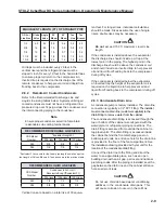
4.1.1.5
A/C Grouping pLAN Operation
Multiple A/C system controllers can be connected
(grouped) to a pLAN local network, allowing the
communication of data and information from each
controller to a central control terminal or Lead controller.
The Lead controller display screens can be used to
monitor and adjust group control variables for the
individual system controllers. Each
E2
controller
connected to the pLAN network is to be identifi ed with its
own unique address.
Multiple A/C units consisting of up to eight (8) STULZ
precision air conditioners equipped with like controllers
may be controlled and monitored via the
E2
series
controller. With multiple A/C units each unit can
selectively be confi gured as "Active" to operate as a
primary A/C, "Capacity Assist" for staged operation
or as "Standby" to come online in case of a failed air
conditioning unit to ensure continuous availability.
The controller may also be confi gured to rotate units
with timed duty cycling to promote equal run-time and
assure that each A/C unit within the rotating group is
operationally exercised on a periodic timed basis.
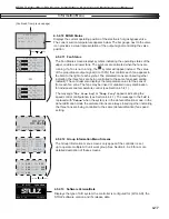
4.1.2 User Interface Display Panel
Your unit is equipped with an interface display panel typi-
cally mounted on the front panel of the A/C unit.
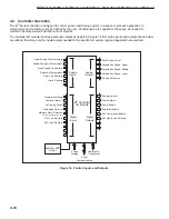
Figure 10- User Interface Display Panel
The user interface display panel features an easy to
read, backlit liquid-crystal alphanumeric display equipped
with LED illuminated function keys. The screens that
appear on the user interface display panel present data
that originates from the controller I/O module (Figure
10). The controller is operated via a 6-key menu-driven
loop structure and offers an alarm log plus four different
interface menu levels to the operator;
Information,
Control, Service, and Factory
. These menus permit
the user to easily view, control and confi gure operating
parameters for the A/C unit. (See Menu Selections,
Figure 13.)
4.1.2.1 Function
Keys
KEY FUNCTION
Accesses the active alarm screen(s)
Silences audible alarms
Resets active alarms in the alarm menu
Accesses the main menu
Prg
Illuminates yellow when unit is on
Returns to the previous menu level
Cancels a changed entry
Steps to the next screen in the display menu
Increases the value of a modifi able numeric fi eld
Starts/Stops system operation
Accepts current value of a modifi able fi eld
Advances the cursor to the next active alarm screen
Steps back to the previous screen in display menu
Decreases the value of a modifi able numeric fi eld
Esc
4.1.2.2 Contrast
Adjustment
Press and hold the ( ) and (
Prg)
keys; then use the Up
( ) and Down
( )
keys to adjust the contrast.
4.1.2.3 Alarms
Alarm conditions activate a red LED indicator that
backlights the alarm function key. As an option, an alarm
condition may also be enunciated by an audible alarm
signal. An alarm is acknowledged by pressing the alarm
key. This calls up alarm display screen(s) that provide a
text message detailing the alarm condition(s). After an
alarm condition is corrected, the alarm can be cleared by
pressing the alarm key.
Содержание CyberRow DX CRS-042-G
Страница 94: ......


