STULZ CyberRow DX Series Installation, Operation & Maintenance Manual
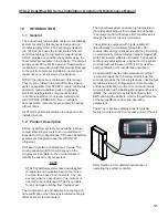
During start up, the fans begin operating in stages
with fi ve second time delays. The middle fan starts
fi rst, then the upper fan, then the lower fan. The
system controller monitors fan operation. If one or
two of the fans fail to operate, the controller alerts the
operator with an alarm message and increases the
speed of the remaining fan(s) to compensate for the
loss of air fl ow.
The system controller may be used to confi gure the
fans for zone temperature control with independently
variable fan speeds or with all three fans operating at
the same variable speed (See Section 4.4.4).
1.5.7 Temperature/Humidity Sensors
Control and alarm recognition takes place by means of
the controller analyzing signal inputs from the sensors to
manage the operation of the A/C unit consistent with the
setpoints entered in the system controller. The system
controller monitors three NTC type temperature sensors
and a 4-20 mA temperature/humidity (T/H) sensor.
The NTC sensors are factory installed in pre-determined
supply air fan zones inside the cabinet. Each NTC
sensor is used by the system controller to manage the
speed of the fan for that zone to meet the supply air
setpoint temperature. The return air is monitored by a
temperature/humidity (T/H) sensor which is typically
mounted inside the cabinet. As an option, the return
air T/H sensor may be removed from the cabinet and
mounted in the hot aisle. The actual sensor values may
be viewed from the controller user interface display using
the Information menu loop.
1-8
1.6 Optional
Equipment
1.6.1 Remote Mounted Supply
Temperature/Humidity
Sensor
As an option, a supply T/H sensor may be provided
for fi eld installation (see Section 2.6.2). This is to
be mounted in the supply (cold aisle) space for
monitoring or control purposes. Refer to the electrical
drawing supplied with your unit for wiring details
specifi c to your system.
1.6.2 Water Detector
As an option, STULZ offers spot type or strip/cable
type water detectors (see Section 2.6.1). Upon sens-
ing a leak, the water detector control circuit will signal
the system controller of the alarm condition. The
system controller is programmed to shut down the
compressor and the fans when a leak is detected.
1.6.3 Smoke Detector
Optionally mounted in the return air side of the cabinet,
a photo-electric smoke detector is used to sense the
presence of smoke and signal the controller when a
smoke alarm condition exists and shuts down the air
conditioner.
1.6.4 Firestat
Optionally mounted in the return air side of the cabi-
net, a fi re detector senses high return air temperature
and signals the controller when a fi re alarm condition
exists and shuts down the air conditioner.
Содержание CyberRow DX CRS-042-G
Страница 94: ......


