


STULZ CyberRow DX Series Installation, Operation & Maintenance Manual
1-6
1.5 General
Design
The STULZ
CyberRow
unit is housed in a steel frame type cabinet rated for indoor use. The exterior of the cabi-
net is coated with a powder coat fi nish to protect against corrosion. Removable access panels are located on
the front and rear of the cabinet for easy access to all components. Operator controls are conveniently located
on the front of the cabinet.
NOTE
Customer specifi ed non standard features or design variations may not be described in this manual. Refer
to the installation and/or electrical drawings supplied with your unit for details of additional feature(s). In
some cases, an addendum to this manual may also be included to further describe the feature(s).
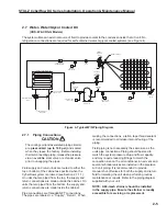
Figure 1 depicts a typical internal layout and identifi es the major components of a typical CyberRow unit utilizing
Direct Expansion (DX) refrigerant. The location of some components may vary depending on the cooling
confi guration selected (Water, Water/Glycol or Air Cooled).
NOTE:
1. CABINET ACCESS PANELS REMOVED TO SHOW INTERNAL PARTS.
AIR FILTERS
SWING-OUT
HINGE
EC FAN (3)
ELECTRIC BOX
DISCONNECT
SWITCH
COMPRESSOR
PIPE TRANSITION
PLATE
EVAPORATOR
COIL
TEMPERATURE
SENSOR
TEMPERATURE
SENSOR
TEMPERATURE
SENSOR
T/H SENSOR
LEVEL
ADJUSTMENT
SCREW (4)
CASTER
HOUSING (4)
DRAIN PANS
CONDENSER
(CRS-W & CRS-G
UNITS ONLY)
FLOAT SWITCH
ELECTRICAL
KNOCK-OUTS
ELECTRICAL
KNOCK-OUTS (IN
BOTTOM OF BOX)
PIPING/ELECTRICAL
KNOCK-OUTS
(IN FLOOR OF CABINET)
Figure 1- Typical Internal Layout- CRS-042/084
Содержание CyberRow DX CRS-042-G
Страница 94: ......


