Index:
Erstellt: 06/17
2017-07-03 installation instructions rudder angle indication systems.docx
Page 6
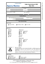
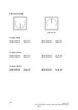
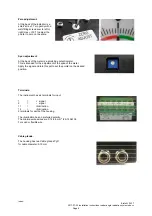
Zero adjustment:
At the back of the indicator is a
small “screw”. Turn gently with a
well-fitting screwdriver to left or
right (max +/-30°) to adjust the
pointer to zero on the scale.
Span adjustment
:
At the back of the meter is a small blue potentiometer.
This is intended for the adjustment of the span of the meter.
Apply the signal and turn this pot to set the pointer on the desired
position.
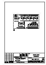
Terminals:
The instrument has six terminals for input
1
=
+ signal
2
=
- signal
11 = illumination
12 =
illumination.
2 terminals for earth of the housing
The illumination has no preferred polarity.
The min/max wires sizes are 0,14-2.5 mm
2
(26-14 AWG).
For solid or flexible wire.
Cable glands:
The housing has two Cable glands Pg11
for cable diameter: 5-10mm
Содержание Rudder Angle Indicator System
Страница 18: ...056357 B RAIS 1 10 Declaration of Conformity...
Страница 20: ...056357 B RAIS 2 2 Normal Operational Mode...
Страница 26: ...056357 B RAIS 3 6 Viewing RAC Errors through SUSI...
Страница 28: ...056357 B RAIS 4 2 Maintenance by Service Personnel...
Страница 58: ...056357 B RAIS 7 4 General Troubleshooting Instructions...
Страница 64: ...056357 B RAIS 8 6 Replacing Alarm Output Relays...
Страница 95: ......
Страница 96: ......
Страница 97: ......
Страница 98: ......
Страница 99: ......
Страница 100: ......
Страница 101: ......
Страница 102: ......
Страница 103: ......
Страница 104: ......
Страница 105: ......
Страница 106: ......
Страница 107: ......
Страница 108: ......
Страница 109: ......
Страница 110: ......
Страница 111: ......
Страница 112: ......
Страница 113: ......
Страница 114: ......
Страница 115: ......


