056357/B
RAIS
6-4
Initial system configuration
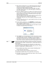
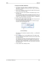
11. If you clicked
in the previous step, a dialogue box will pop
up, asking whether the parameters should be saved as default set-
tings for this device:
Click
. to save the parameters as default settings or
click
to cancel.
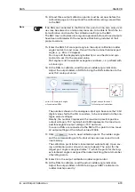
12. If you clicked
in the previous step, the default settings are
now written to a file named “RACdefault.xml“ in the sub-directory
“Parameter Files” in SUSI’s installation directory.
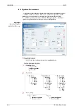
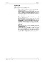
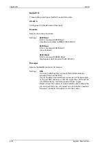
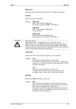
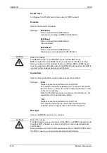
13. Using the Main page controls, set all system parameters as required.
An overview and detailed descriptions of the system parameters are
given below (see “System Parameters” on page 6-6).
14. When all parameters are set as required, click
to transfer the
settings to the RAC.
15. Carry out the initial calibration procedure (see “Initial Calibration” on
page 6-16).
If the steering gear is operative and permission is given to actuate
the rudder, start with the input calibration.
If the rudder cannot be actuated now, an input calibration may be
carried out using dummy input signals (see “Input Calibration using
Dummy Values” on page 6-24).
Continue with the output calibration, calibrating at least one of the
analogue outputs. If no RAI is connected to the RAC yet, dummy val-
ues may be supplied for the output calibration.
16. When the in- and output calibration procedures have been fully com-
pleted and all components of the RAI system are operational, carry
out a brief function-check.
Note
If a default parameter file for the Rudder Angle Calibrator already exists,
e. g. if the service PC previously been used to service another RAC, the
warning message described above will not appear.
In this case, do not write back settings to the RAC before all system
parameters have been set as required for the installation at hand.
Note
The setting of the system parameters and the input and output calibra-
tion may be carried out at different points in time.
However, the Rudder Angle Calibrator’s initial configuration is complete
only if all three of these tasks have been completed successfully and it
has been checked that the required calibration accuracy is attained with
all components of the RAI system being connected and operational.
Содержание Rudder Angle Indicator System
Страница 18: ...056357 B RAIS 1 10 Declaration of Conformity...
Страница 20: ...056357 B RAIS 2 2 Normal Operational Mode...
Страница 26: ...056357 B RAIS 3 6 Viewing RAC Errors through SUSI...
Страница 28: ...056357 B RAIS 4 2 Maintenance by Service Personnel...
Страница 58: ...056357 B RAIS 7 4 General Troubleshooting Instructions...
Страница 64: ...056357 B RAIS 8 6 Replacing Alarm Output Relays...
Страница 95: ......
Страница 96: ......
Страница 97: ......
Страница 98: ......
Страница 99: ......
Страница 100: ......
Страница 101: ......
Страница 102: ......
Страница 103: ......
Страница 104: ......
Страница 105: ......
Страница 106: ......
Страница 107: ......
Страница 108: ......
Страница 109: ......
Страница 110: ......
Страница 111: ......
Страница 112: ......
Страница 113: ......
Страница 114: ......
Страница 115: ......


