background image

056357/B

RAIS

6-20

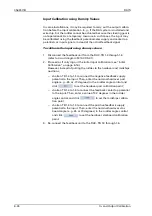
In- and Output Calibration

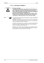
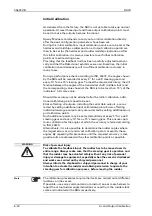
In case no RAIs are connected to the RAC at this point in time, leave 
all output settings at the default value of 2048.

20. Click 

 to set a new calibration point.

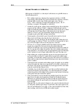
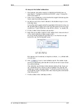
21. Enter the RAI’s full scale starboard angle in the output calibration 

rudder angle control.

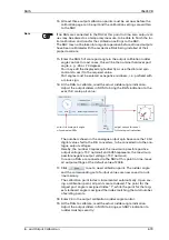
22. Adjust the output sliders in SUSI to bring the RAI’s indication to the 

exact full scale starboard value:

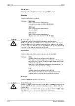
In case no RAIs are connected to the RAC at this point in time, leave 
all output settings at the default value of 2048.

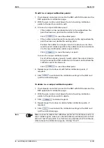
23. Click 

 to set a new calibration point.

24. Check that all output calibration points have been stored correctly:

The calibration point index should now read “4”.

Scroll down the list of calibration points with the spin control and 
verify that:

For points 1 to 3, the rudder angles displayed are those you 
entered for the full scale and midships indications. The input 
controls will be greyed-out for the saved points.

For each point, the calibrated RAIs indicate the respective rudder 
angle exactly.

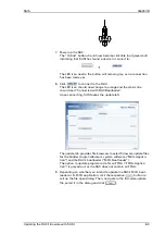
25. Click 

 to quit the calibration page and write the calibration 

settings to the RAC.

If the above steps have been carried out with all components of the 
RAI system being operational, the initial calibration is now complete.

enter zero

(rudder midships)

45

45

30

30

15

15

0

RAI

adjust output for exact
rudder midships indication

45

45

30

30

15

15

0

RAI

adjust output for exact
full-scale stb. indication

enter full scale stb. angle
of connected RAIs

Содержание Rudder Angle Indicator System

Страница 1: ...ltmanstr 19 D 20097 Hamburg Germany Tel 49 40 299 00 0 Fax 49 40 299 00 146 E mail service eu sperry ngc com Operation Installation and Service Manual RUDDER RUDDER RUDDER RUDDER X RUDDER RUDDER Rudde...

Страница 2: ...es Reproduction of this document for resale or commercial gain is expressly pro hibited Specifications were correct at time of press but may be varied in accordance with NGSM BV s policy of continuous...

Страница 3: ...tion 3 1 Alarm Status Output 3 1 Serial Data Alarm Output 3 1 3 2 Alarm Numbers 3 3 3 3 Viewing RAC Errors through SUSI 3 5 Chapter 4 Scheduled Maintenance 4 1 Maintenance by Shipboard Personnel 4 1 4...

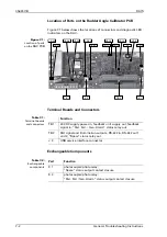
Страница 4: ...ation using Dummy Values 6 24 Chapter 7 Troubleshooting 7 1 General Troubleshooting Instructions 7 1 Location of Parts on the Rudder Angle Calibrator PCB 7 2 Terminal Boards and Connectors 7 2 Exchang...

Страница 5: ...d could result in injury or death of personnel CAUTION A Caution notice contains an operating or main tenance procedure practice condition state ment etc which if not strictly observed could result in...

Страница 6: ...ularly check the indication of the RAIs against the actual position of the rudder angle shaft to make sure that calibration is applied properly and the specified accuracy is maintained Note A given al...

Страница 7: ...nic circuitry WARNING Risk of personal injury To calibrate the feedback input the rudder has to be moved over its entire range Always make sure that the steering gear is operative and that the rudder...

Страница 8: ...setting is INACTIVATED when the RAC is used on a ship under wheelmark certification CAUTION Risk of misusage The RS 422 output 1 and RS 422 output 2 of the RAC is not MED compliant in case 38400 baud...

Страница 9: ...der Angle Indicators RAI and a series of Rudder Angle Feedback Units RAFU including limit switches and lever linkages Not Intended Use The Sperry Marine Rudder Angle Indicator System RAIS is designed...

Страница 10: ...H 47253 12 HH For further details see Declaration of Conformity on page 1 9 The RAC is used to attain ISO_20673 compliant overall calibration accu racy in RAI systems with conventional moving coil ind...

Страница 11: ...rre sponding rudder angle for a number of significant rudder positions The actual feedback voltage is thus converted to a digital rudder angle value and automatically corrected according to the stored...

Страница 12: ...RAI third party three face panorama type example 060396 0000 000 range 45 060397 0000 000 range 70 RAI standard type third party example 060327 0000 000 060328 0000 000 060334 0000 000 060335 0000 00...

Страница 13: ...own 074723 0000 000 Lever Linkage 020508 0000 000 022501 0000 000 System Component Name Stock No Note For all details regarding the Rudder Angle Indicators refer to the third party documentation from...

Страница 14: ...oltage 24 VDC RAC max ripple content 10 20 Vpp RAC power consumption 3 W max Rudder Angle Indicator System power consumption 15 W max in total for rudder angle indicator illumi nation via RAC RAC Magn...

Страница 15: ...ngle RSA set alarm state ALR CAUTION Risk of misusage The RS 422 output 1 and RS 422 output 2 of the RAC is not MED compliant in case 38400 baud are selected as interface setting Always make sure that...

Страница 16: ...ta RAC Service I O Port USB service port Connects to a Windows host PC through a vendor specific USB communications device class driver The Rudder Angle Calibra tor is accessed via the SUSI applicatio...

Страница 17: ...is equipment has been tested to verify compliance with the Regulations and Testing Standards according to implementing regula tion EU 2017 306 as per EC Type Examination Certificate Module B and QS Ce...

Страница 18: ...056357 B RAIS 1 10 Declaration of Conformity...

Страница 19: ...es in and output calibration according to the stored cali bration tables at all times If no errors are present the only noticeable effect of the RAC being included in the RAIS will be an increased acc...

Страница 20: ...056357 B RAIS 2 2 Normal Operational Mode...

Страница 21: ...nce is transmitted con taining the corresponding alarm number and description text The alarm will be marked as active and not acknowledged When a given alarm condition is no longer present the RAC tra...

Страница 22: ...RAIS 3 2 Alarm Indication Note The RAC does not support remote alarm acknowledgement via the ACK sentence Alarms will be transmitted as being not acknowl edged even if acknowledged locally at the rece...

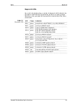
Страница 23: ...cy clically when no ac tive alarm is present none group 400 data I O errors NMEA crosslink between starboard and port RACs in dual rudder system 401 wrong checksum RxD1 faulty checksum in NMEA senten...

Страница 24: ...e of data source at the RS 422 input Only the other side s RAC in a dual rudder system may be connected to input 445 error in received NMEA message malformed NMEA sentence received at the RS 422 input...

Страница 25: ...rument application SUSI provides an Errors page which displays current state and counts the occurrence of the alarms listed in table 3 1 above Figure 3 1 SUSI s Error Page for the RAC For more informa...

Страница 26: ...056357 B RAIS 3 6 Viewing RAC Errors through SUSI...

Страница 27: ...anical damage Check the connectors at the RAC the rudder angle feedback unit and the RAIs for signs of corrosion loose contacts etc Inspect the feedback unit and the feedback linkage in particular for...

Страница 28: ...056357 B RAIS 4 2 Maintenance by Service Personnel...

Страница 29: ...r inclined 5 2 Electrical Installation Rudder Angle Calibrator Wire up the system according to the connection diagrams and other relevant documents provided DANGER Life danger through electrical shock...

Страница 30: ...bears the risk of malfunc tion of the steering gear in case of wire breaks or short circuits resulting in possible injury and or damage Under no circumstances must the RAC be connected to a rudder an...

Страница 31: ...e feedback input the rudder has to be moved over its entire range Always make sure that the steering gear is operative and that the rudder may be actuated safely without any risk of personal injury or...

Страница 32: ...B cable Do not plug in the cable yet 3 Power up the RAC 4 At the PC start up the SUSI application A login dialogue pops up 5 Enter the PIN 20097 This will start up SUSI in the service mode Click at th...

Страница 33: ...ow change to green and the status line should read Connected with RAC Upon connection SUSI populates the Application tab with the RAC application controls and displays the application s Main Page 10 I...

Страница 34: ...ried out using dummy input signals see Input Calibration using Dummy Values on page 6 24 Continue with the output calibration calibrating at least one of the analogue outputs If no RAI is connected to...

Страница 35: ...uration and calibration settings from the RAC back into SUSI s runtime memory A dialog box will pop up asking whether these parameters should be saved as default settings for this device 21 Click to s...

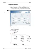
Страница 36: ...ings and the Relay Setup Figure 6 1 Controls on the RAC application Main page Feedback Type port rudder starboard rudder single rudder Serial I O RS 422 In Baudrate 38400 9600 4800 Messages RSA RS 422...

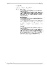
Страница 37: ...ering gear The RAC s serial data outputs transmit the own rudder angle as the starboard or single rudder sensor angle in the RSA sentence If a valid port rudder angle is read from a sec ond Rudder Ang...

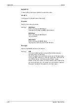
Страница 38: ...a is received at 38400 Baud high speed not compliant to IEC 61162 2 Messages Selects the NMEA sentences to receive Settings RSA In a dual rudder system evaluate the RSA sentence received from another...

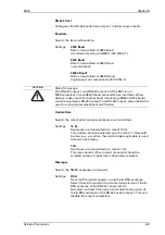
Страница 39: ...tput when the RAC is used on a ship under wheelmark certification Update Rate Selects the rate at which output sentences are transmitted Settings 10 Hz Sentences are transmitted at a rate of 10 Hz Thi...

Страница 40: ...lmark certification Update Rate Selects the rate at which output sentences are transmitted Settings 10 Hz Sentences are transmitted at a rate of 10 Hz This option should be selected only if a rate of...

Страница 41: ...the output is connected to a VDR it is recommended to limit the message update rate to 1 Hz and to disable transmission of data which is already fed to the VDR from another source Disabling both opti...

Страница 42: ...s entire range Always make sure that the steering gear is operative and that the rudder may be actuated safely without any risk of personal injury or damage to equipment especially when the vessel is...

Страница 43: ...cator dial and spin box Calibration Point spin box Output Digit sliders and spin boxes Delete and Save buttons 2 2 Note Accessing the calibration page puts the Rudder Angle Calibrator into a special c...

Страница 44: ...the optimum calibration is achieved at the rudder angles where the calibration accuracy is to be checked later according to ISO 20673 Additional calibration points may be added later up to a total of...

Страница 45: ...rwrit ten if a new point is added for exactly the same rudder angle value The analogue in or output values associated with a given calibration point however may be freely edited after the point has be...

Страница 46: ...to be set Errors affecting all outputs including the serial data outputs are cor rected by setting additional input calibration points Errors affecting individual analogue outputs only are corrected...

Страница 47: ...hardover port position 5 Read the exact rudder angle from the rudder stock scale and enter it in the input calibration rudder angle control You may edit the displayed angle directly or use the dial a...

Страница 48: ...should now read 4 Scroll down the list of calibration points with the spin control and verify that For points 1 to 3 the rudder angles displayed are those you entered for the hardover and midships po...

Страница 49: ...e no RAIs are connected to the RAC at this point in time leave all output settings at the default value of 2048 17 Click to set a new calibration point The rudder angle and the corresponding set of ou...

Страница 50: ...ectly The calibration point index should now read 4 Scroll down the list of calibration points with the spin control and verify that For points 1 to 3 the rudder angles displayed are those you entered...

Страница 51: ...ccur and set calibration points at exactly these angles Repeat this procedure until the required accuracy is met This ensures good calibration with as few calibration points as possible 28 If required...

Страница 52: ...total up to 73 points may be entered 6 Click to write back the calibration settings to the RAC and quit the calibration page To add output calibration points 1 If not already connected connect to the...

Страница 53: ...s you wish to edit adjust the output slider to bring the respective RAI s indication to the exact value where the calibration point has been set Click to save the edited point 4 Repeat steps 2 to 3 ab...

Страница 54: ...out the initial input calibration see Initial Calibration on page 6 16 However instead of putting the rudder to the hardover and midships positions shorten TB 1 4 to 1 5 to connect the negative feedba...

Страница 55: ...s must be checked with a voltmeter The data content on serial I O lines must be checked with the aid of suitable analyzing tools such as PC based protocol interpreters or terminal programs Software ai...

Страница 56: ...nents Table 7 2 Exchangeable components TB 1 TB 2 CR 34 CR 20 CR 17 J 3 CR 4 CR 33 CR 29 CR 23 CR 16 CR 13 CR 12 CR 9 CR 28 K 2 K 1 Function TB 1 24 VDC supply power in feedback unit supply out feedba...

Страница 57: ...Spare on relay attracted CR 9 green activity on RS 422 input CR 12 green system mode status indication both flashing power up in progress both off normal operation mode both on error reading setup dat...

Страница 58: ...056357 B RAIS 7 4 General Troubleshooting Instructions...

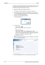
Страница 59: ...eleased for the RAC authorized field service personnel will be provided with the required files upon request DANGER Life danger through electrical shock Certain alarm devices may operate with hazardou...

Страница 60: ...hat the port is freely accessible for plug ging and unplugging the USB cable 3 At the PC start up the SUSI application A login dialog pops up 4 You may either Enter the PIN 20097 This will start up SU...

Страница 61: ...d with RAC Bootloader Upon connecting SUSI opens the update tab The update tab provides file browsers to select firmware update files for the Rudder Angle Calibrator s system software MCU Applica tion...

Страница 62: ...en the update is complete unplug the USB cable at the PC and at the RAC s service port 12 The RAC now reboots with the new firmware Note The file open dialogue searches for files with the extension up...

Страница 63: ...Relays The alarm output relays K1 and K2 are socketed solid state relays in a 6 pin DIL package In case of failure these components can easily be replaced against a new ones Both relays are photocoupl...

Страница 64: ...056357 B RAIS 8 6 Replacing Alarm Output Relays...

Страница 65: ...ACK Acknowledge alarms ADA Name of a Programming Language AIS Automatic Identification System ALR NMEA sentence for alarm status information AMS Alarm Management System ANSI American National Standar...

Страница 66: ...er ground COMP Compass Comp Mon Compass monitor CONST Constant contd Continued CORR Correction cos Cosine CR Carriage return CSU Compass Sensor Unit processor D D00 D00 D32 D Code Fault code DAC Digit...

Страница 67: ...ronmental conditions EM Log Electromagnetic speed log EN European Norm ERR STAT BITS Validity check of fiber optic sensor data status ESD electrostatic discharge ext External Ext External Ext Sel Exte...

Страница 68: ...Satellite System GPS Global Positioning System GPS Global Positioning System GPS AIS Global Positioning System Automatic Identification System GSR Gyrosphere service report GT Gross tonnage H HCS Hea...

Страница 69: ...fice IMO International Maritime Organization IMU Inertial Measurement Unit INS Integrated navigation system INT HDG ONLY Internal heading only INT EXT HDG Internal or external heading IP International...

Страница 70: ...gation C LSB Least significant Bit M Mag Magnetic Mag Hdg Inp Magnetic heading input MAGN Magnet Magn Cal Tab Magnetic compass calibration table Magn DEV Magnetic deviation Magn VAR Magnetic variation...

Страница 71: ...ss notation with requirements for ships largely operating as support vessels for various offshore operations Nav Navigation n c Normally closed NC Normally closed NFU None follow up NG NAVIGAT NG 100...

Страница 72: ...OUTP Output P p Pulse P Gnd Power ground P N Part number PAL Pre programmed IC PCB Printed circuit board PLATH Binary protocol of company C Plath PLCC Plastic leaded chip carrier POS Position POSITIO...

Страница 73: ...ion NMEA sentence B RMC Recommended minimum navigation information NMEA sentence C RMS Root mean square ROM Read Only Memory ROR Rudder order status ROT Rate of turn ROTI Rate of turn indicator rpm Re...

Страница 74: ...d STW Speed through water ship s speed as measured rela tive to the water SUSI Sperry universal service instrument SVDR Simplified voyage data recorder T TB TB 3 11 external input port TB Terminal blo...

Страница 75: ...gement system VMS ECDIS Voyage management system electronic chart display and information system VOSS Vessel optimization safety system Vpp Voltage peak to peak VTG Velocity through ground VTS Vessel...

Страница 76: ...056357 B RAIS XII Abbreviations Z Z DO 160 Section Z DO 160E Environmental Conditions and Test Procedures for Airborne Equipment...

Страница 77: ...in the ship s file When permanent changes are made to the system configuration please return an updated copy of the Setup Table to Sperry Marine Designation Drawing No Faiveley Mors Smitt Rudder Angle...

Страница 78: ...112 04 Rudder Angle Indicator System Single Rudder up to 6 indicators Standard Connection Drawing 5014 0153 11 Rudder Angle Indicator System Single Rudder more than 6 indicators Standard Connection Dr...

Страница 79: ...te Signature Installation Reference RAC Serial Number Location Software Version System Parameter Settings Feedback Type port rudder starboard rudder single rudder Serial I O RS 422 In Baudrate 38400 9...

Страница 80: ...l 49 40 29900 0 Fax 49 40 29900 146 E mail service de sperry ngc com Rudder Angle Calibrator RAC Setup Table Rud Angle A D Digits Rud Angle A D Digits 1 2 3 4 5 6 7 8 9 10 11 12 13 14 15 16 17 18 19 2...

Страница 81: ...e Office Woltmanstr 19 20097 Hamburg Germany Tel 49 40 29900 0 Fax 49 40 29900 146 E mail service de sperry ngc com Output Calibration Table Rudder Angle Digits Out 1 Digits Out 2 Digits Out 3 Digits...

Страница 82: ...ltmanstr 19 20097 Hamburg Germany Tel 49 40 29900 0 Fax 49 40 29900 146 E mail service de sperry ngc com Output Calibration Table continued Rudder Angle Digits Out 1 Digits Out 2 Digits Out 3 Digits O...

Страница 83: ...Index Erstellt 06 17 2017 07 03 installation instructions rudder angle indication systems docx Page 1 Installation instructions Rudder Angle Indication Systems...

Страница 84: ...0000 000 Range 45 060335 0000 000 Range 70 060331 0000 000 Range 45 060337 0000 000 Range 70 Frontsize 144x144 060338 0000 000 Range 45 060339 0000 000 Range 70 060340 0000 000 Range 45 060341 0000 0...

Страница 85: ...7 2017 07 03 installation instructions rudder angle indication systems docx Page 3 Panel cutout Frontsize Dimensions mm A 96x96 92 0 8 144x144 138 1 192x192 186 1 Mounting withe fastening clamp Mounti...

Страница 86: ...o zero on the scale Span adjustment At the back of the meter is a small blue potentiometer This is intended for the adjustment of the span of the meter Apply the signal and turn this pot to set the po...

Страница 87: ...4x144mm 060327 0000 000 Range 45 060328 0000 000 Range 70 060325 0000 000 Range 45 060326 0000 000 Range 70 Scale 192mmx192mm 060357 0000 000 Range 45 060359 0000 000 Range 70 060332 0000 000 Range 45...

Страница 88: ...eter is a small blue potentiometer This is intended for the adjustment of the span of the meter Apply the signal and turn this pot to set the pointer on the desired position Terminals The instrument h...

Страница 89: ...nstructions rudder angle indication systems docx Page 7 Instructions for the exchange of the measuring instrument Tools you need inbus 6mm socket wrench 5 5mm small screwdriver Open the case 4x mm inb...

Страница 90: ...03 installation instructions rudder angle indication systems docx Page 8 Disconnect cable blue 2 red 1 black 11 gray 12 Instrument with disconnected cable Disconnect the 8x screw which fixing the ins...

Страница 91: ...06 17 2017 07 03 installation instructions rudder angle indication systems docx Page 9 Remove the instrument from the housing Check the new instrument is the rubber seal present Put the new instrument...

Страница 92: ...allation instructions rudder angle indication systems docx Page 10 8x screw which fixing the instrument 8x M3 screw and key 5 5mm connect cable blue 2 red 1 black 11 gray 12 close the case 4x mm inbus...

Страница 93: ...7 07 03 installation instructions rudder angle indication systems docx Page 11 Three face panorama rudder angle indicator Scale 144x144mm 060396 0000 000 Range 45 060397 0000 000 Range 70 Drilling sch...

Страница 94: ...ver the potentiometer SPAN1 for PORT side or SPAN2 for STBD side to left or right to adjust the pointer to zero on the scale The instrument must be supplied with 24V For span adjust PORT side apply fu...

Страница 95: ......

Страница 96: ......

Страница 97: ......

Страница 98: ......

Страница 99: ......

Страница 100: ......

Страница 101: ......

Страница 102: ......

Страница 103: ......

Страница 104: ......

Страница 105: ......

Страница 106: ......

Страница 107: ......

Страница 108: ......

Страница 109: ......

Страница 110: ......

Страница 111: ......

Страница 112: ......

Страница 113: ......

Страница 114: ......

Страница 115: ......

Страница 116: ...Grumman Sperry Marine B V Representative Office Woltmanstr 19 D 20097 Hamburg Germany Tel 49 40 299 00 0 Fax 49 40 299 00 146 E mail service eu sperry ngc com Sperry Marine Service www sperrymarine co...

Отзывы: