background image

34

M2i.60xx / M2i.60xx-exp Manual

Linux

Software Driver Installation

Library only

The kernel driver module only contains the basic hardware functions that are necessary to access locally installed card level products. The 
main part of the driver is located inside a dynamically loadable library that is delivered with the driver. This library is available in 3 different 
versions:

•  spcm_linux_32b+5.so - supporting +.so.5 on 32 bit systems
•  spcm_linux_32b+6.so - supporting +.so.6 on 32 bit systems
•  spcm_linux_64b+6.so - supporting +.so.6 on 64 bit systems

The matching version is installed automatically in the /usr/lib directory by the kernel driver install script for card level products. The library 
is renamed for easy access to libspcm_linux.so. 

For digitizerNETBOX products the library is installed with a separate install script:

To access the driver library one must include the library in the compilation:

To start programming the cards under Linux please use the standard C/C++ examples which are all running under Linux and Windows.

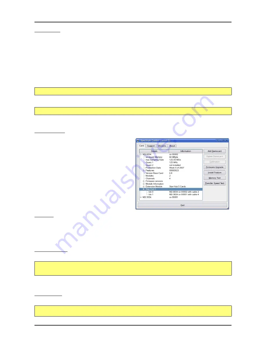
Control Center

The Spectrum Control Center is also available for Linux and needs to 
be installed separately. The features of the Control Center are de-
scribed in a later chapter in deeper detail. The Control Center has 
been tested under all Linux distributions for which Spectrum delivers 
pre-compiled kernel modules. The following packages need to be in-
stalled to run the Control Center:

• X-Server
• expat
• freetype
• fontconfig
• libpng
•  libspcm_linux (the Spectrum linux driver library)

Installation

Use the supplied packages in either *.deb or *.rpm format found in the driver section of the CD by double clicking the package file root 
rights from a X-Windows window.

The Control Center is installed under KDE/Gnome in the system/system tools section. It may be located directly in this menu or under a „More 
Programs“ menu. The final location depends on the used Linux distribution. The program itself is installed as /usr/bin/spcmcontrol and may 
be started directly from here.

Manual Installation

To manually install the Control Center, first extract the files from the rpm matching your distribution:

You get the directory structure and the files contained in the rpm package. Copy the binary spcmcontrol to /usr/bin. Copy the .desktop file 
to /usr/share/applications. Run ldconfig to update your systems library cache. Finally you can run spcm_control.

Troubleshooting

If you get a message like the following after starting spcm_control:

sh install_libonly.sh

gcc -o test_prg -lspcm_linux test.cpp

rpm2cpio spcmcontrol-{Version}.rpm > ~/spcmcontrol-{Version}.cpio
cd ~/
cpio -id < spcmcontrol-{Version}.cpio

spcm_control: error while loading shared libraries: libz.so.1: cannot open shared object file

: No such file 

or directory

Содержание M2i.60xx

Страница 1: ...NY PHONE 49 0 4102 6956 0 FAX 49 0 4102 6956 66 E MAIL info spec de INTERNET http www spectrum instrumentation com M2i 60xx M2i 60xx exp fast 14 bit arbitrary waveform generator D A converter board for PCI X PCI and PCI Express bus Hardware Manual Software Driver Manual English version June 2 2015 ...

Страница 2: ...s 8 and Windows 10 are trademarks registered trademarks of Microsoft Corporation LabVIEW DASYLab Diadem and LabWindows CVI are trademarks registered trademarks of National Instruments Corporation MATLAB is a trademark registered trademark of The Mathworks Inc Keysight VEE VEE Pro and VEE OneLab are trademarks registered trademarks of Keysight Technologies Inc FlexPro is a registered trademark of W...

Страница 3: ...ions 20 Installing a board with digital inputs outputs mounted on an extra bracket 22 Installing a board with option BaseXIO 23 Installing multiple boards synchronized by star hub option 24 Software Driver Installation 25 Interrupt Sharing 25 Important Notes on Driver Versions 2 22 and Control Center 1 41 and newer 25 Windows 2000 26 Installation 26 Version control 26 Driver Update 27 Windows XP 3...

Страница 4: ...64 Bit 44 C for NET 44 Other Windows C C compilers 32 Bit 44 Other Windows C C compilers 64 Bit 44 National Instruments LabWindows CVI 45 Driver functions 45 Borland Delphi Pascal Programming Interface 50 Driver interface 50 Examples 51 Visual Basic Programming Interface and Examples 52 Driver interface 52 Examples 53 NET programming languages 54 Library 54 Declaration 54 Using C 54 Using Managed ...

Страница 5: ...ling 79 Output latency 83 Data organisation 84 Sample format 84 Hardware data conversion 84 Clock generation 85 Overview 85 The different clock modes 85 Clock Mode Register 86 Internally generated sample rate 86 Standard internal sampling clock PLL 86 Using plain Quartz1 without PLL 87 Using plain Quartz2 without PLL optional 87 External reference clock 87 External clocking 88 Direct external cloc...

Страница 6: ...ampling Feature 114 Electrical specifications 114 Option Star Hub 115 Star Hub introduction 115 Star Hub trigger engine 115 Star Hub clock engine 116 Software Interface 116 Star Hub Initialization 116 Setup of Synchronization and Clock 118 Setup of Trigger 119 Trigger Delay on synchronized cards 119 Run the synchronized cards 119 Error Handling 120 Excluding cards from trigger synchronization 120 ...

Страница 7: ...32 Background 132 Setup on Windows systems 132 Setup on Linux systems 132 Usage of the buffer 133 Pin assignment of the multipin connector 134 Option Digital outputs 134 Pin assignment of the multipin cable 134 IDC footprints 135 Details on M2i cards clock and trigger I O section 136 ...

Страница 8: ...oth standards available for instrumentation boards Special industrial PCs offer up to a maximum of 20 slots The common PCI PCI X bus with data rates of up to 133 MHz x 64 bit 1 GByte s per bus is more and more replaced by the PCI Express standard with up to 4 GByte s data transfer rate per slot The Spectrum M2i boards are available in two versions for PCI PCI X as well as for PCI Express The 100 s...

Страница 9: ...w shows the different available models of the M2i 60xx series They differ in the number mounted generation modules and the number of available channels You can also see the model dependent allocation of the output connectors M2i 6030 M2i 6030 exp M2i 6011 M2i 6021 M2i 6033 M2i 6011 exp M2i 6021 exp M2i 6033 exp M2i 6031 M2i 6031 exp ...

Страница 10: ...10 M2i 60xx M2i 60xx exp Manual Different models of the M2i 60xx series Introduction M2i 6012 M2i 6022 M2i 6034 M2i 6012 exp M2i 6022 exp M2i 6034 exp ...

Страница 11: ... synchronization star hub is used The cable connection of the boards is automatically recognized and checked by the driver when initializing the star hub module So no care must be taken on how to cable the cards The star hub module itself is handled as an additional device just like any other card and the pro gramming consists of only a few additional commands System Star Hub The System Star Hub S...

Страница 12: ...seXIO MMCX connectors are mounted on board To gain easier access these lines are connected to an extra bracket that holds eight SMB male connectors For special purposes this option can also be ordered without the extra bracket and instead with internal cables The shown option is mounted exemplarily on a board with two modules and with the extra bracket Of course you can also combine this option as...

Страница 13: ...example the options Multiple recording Gated Sampling Timestamp and Star Hub 5 are installed The base card version consisting of the hardware version the part before the dot and the firmware version the part after the dot The version of the analog digital front end module Consisting of the hardware version the part before the dot and the firmware version the part after the dot The date of producti...

Страница 14: ...14 M2i 60xx M2i 60xx exp Manual Hardware information Introduction Hardware information Block diagram ...

Страница 15: ...hm load maximum drive strength 128 mA Output delay trigger to 1st sample 15 16 clocks 2 1 channel module Gate end to last replayed sample 15 16 clocks 2 1 channel module Gate end alignment 2 samples 1 ch 1 sample 2 or 4 ch Clock Modes software programmable internal PLL internal quartz external clock external divided external reference clock sync Internal clock range PLL mode software programmable ...

Страница 16: ...put drive strength 32 mA maximum current no 50 Ω loads Bandwidth 30 MHz Output impedance 50 Ohm Max Output Voltage into high impedance load 10 V Max Output Voltage into 50 Ohm load 5 V Gain Error 1 Offset Error 50 mV Short circuit proof Yes Bandwidth 30 MHz Max input voltage 3 V Output impedance 50 Ω Fixed Amplification x 3 3 Max Output Voltage into high impedance load 10 V Max Output Voltage into...

Страница 17: ... for graphic cards only and can not be used EMC Immunity Compliant with CE Mark EMC Emission Compliant with CE Mark Product warranty 2 years starting with the day of delivery Software and firmware updates Life time free of charge PCI PCI X PCI EXPRESS 3 3 V 5 V Total 3 3V 12V Total M2i 6030 256 MS memory 2 6 A 0 4 A 11 6 W 0 4 A 0 9 A 12 1 W M2i 60x1 M2i 60x3 256 MS mem 2 8 A 0 7 A 12 8 W 0 4 A 1 ...

Страница 18: ... xxxx SSHM 1 System Star Hub Master for up to 15 cards in the system and up to 17 systems PCI 32 Bit card sync cables and extra bracket for clock and trigger distribution included M2i xxxx SSHMe 1 System Star Hub Master for up to 15 cards in the system and up to 17 systems PCI Express card sync cables and extra bracket for clock and trigger distribution included M2i xxxx SSHS5 1 System Star Hub Sl...

Страница 19: ...s contain electronic components that can be damaged by electrostatic discharge ESD Before installing the board in your system or even before touching it it is absolutely necessary to bleed off any electrostatic electricity Cooling Precautions The boards of the M2i M3i xxxx series operate with components having very high power consumption at high speeds For this reason it is absolutely required to ...

Страница 20: ...ert the board slowly into your computer This is done best with one hand each at both fronts of the board While inserting the board take care not to tilt the retainer in the track Please take especial care to not bend the card in any direction while inserting it in the system A bending of the card may damage the PCB totally and is not covered by the standard warranty Please be very carefully when i...

Страница 21: ...Installation Installing the board in the system c Spectrum GmbH 21 Installing the M2i M3i xxxx exp PCI Express card in a PCIe x1 slot Installing the M2i M3i xxxx exp PCI Express card in a PCIe x4 x8 or x16 slot ...

Страница 22: ...t the board and the extra bracket slowly into your computer This is done best with one hand each at both fronts of the board While inserting the board take care not to tilt the retainer in the track Please take especial care to not bend the card in any direction while inserting it in the system A bending of the card may damage the PCB totally and is not covered by the standard warranty Please be v...

Страница 23: ...a bracket slowly into your computer This is done best with one hand each at both fronts of the board While inserting the board take care not to tilt the retainer in the track Please take especial care to not bend the card in any direction while inserting it in the system A bending of the card may damage the PCB totally and is not covered by the standard warranty Please be very carefully when inser...

Страница 24: ...back module are available see figure for details on the star hub connector loca tions As some of the synchronization cables are not secured against wrong plugging you should take care to have the pin 1 markers on the multiple connectors and the cable on the same side as the figure on the right is showing Mounting the wired boards Before installing the cards you first need to unscrew and remove the...

Страница 25: ...his happens it is necessary to reconfigure the system in that way that the critical equipment has an exclusive access to an interrupt On most systems the BIOS shows a list of all installed PCI boards with their allocated interrupt lines directly after system start You have to check whether an interrupt line is shared between two boards Some BIOS allow the manual allocation of interrupt lines Have ...

Страница 26: ...ke the M2i 2021 in the exam ple The drivers can be used di rectly after installation It is not necessary to restart the system The installed drivers are linked in the device man ager Below you ll see how to ex amine the driver version and how to update the driver with a newer version Version control If you want to check which driver version is installed in the system this can be eas ily done in th...

Страница 27: ...ect the Driver win32 path on the CD containing the new driver version The new driver version can be used directly after installa tion without restarting the sys tem Please keep in mind to update the driver of all in stalled Spectrum boards Important Notes on Driver Versions 2 22 and Control Center 1 41 and newer With Windows driver version V2 22 and later required internal driver changes were need...

Страница 28: ...e CD that was delivered with the board as installation source The driver files are located on CD in the directory Driver win32 for Windows XP 32 Bit or Driver win64 for Windows XP 64 Bit The hardware assistant shows you the exact board type that has been found like the M2i 2021 in the example The drivers can be used directly after installation It is not necessary to restart the system The installe...

Страница 29: ... boards A new driver version is directly installed from the device manager Therefore please open the properties page of the driver as shown in the section before As next step click on the update driver button and follow the steps of the driver installation in a similar way to the previous board and driver installation Please select the path where the new driver version was unzipped to If you ve go...

Страница 30: ...s control panel as shown on the right Find the above mentioned DPIO Module right click and select Update Driver Software Do not let Windows 7 automatically search the for the best driver be cause it will search the internet and not find a proper driver Please take the option of browsing the computer manually for the driver soft ware instead Allow Windows 7 to search for the most suitable driver in...

Страница 31: ...r with a newer version Version control If you want to check which driver version is installed in the system this can be easily done in the device manager Therefore please start the device manager from the control panel and show the properties of the installed driver On the property page Windows 7 shows the date and the version of the installed driver After clicking the driver details button the de...

Страница 32: ...rocessor single or smp The script will only show matching kernel modules Select the kernel module matching your system The script will then do the follow ing steps copy the selected kernel module to the install directory spcm o or spcm ko copy the helper scripts to the install directory spcm_start sh and spc_end sh copy and rename the matching library to usr lib usr lib libspcm_linux so Udev suppo...

Страница 33: ...e driver you may use the spcm_end sh script Compilation of kernel driver sources option The driver sources are only available for existing customers on special request and against a signed NDA The driver sources are not part of the standard delivery The driver source package contains only the sources of the kernel module not the sources of the library Please do the following steps for compilation ...

Страница 34: ...Center has been tested under all Linux distributions for which Spectrum delivers pre compiled kernel modules The following packages need to be in stalled to run the Control Center X Server expat freetype fontconfig libpng libspcm_linux the Spectrum linux driver library Installation Use the supplied packages in either deb or rpm format found in the driver section of the CD by double clicking the pa...

Страница 35: ...f this still doesn t help please add the library path to etc ld so conf and run ldconfig again If the libspcm_linux so is quoted as missing please make sure that you have installed the card driver properly before If any other library is stated as missing please install the matching package of your distribution libXext so 6 usr X11R6 lib libXext so 6 0x4019e000 libX11 so 6 usr X11R6 lib libX11 so 6...

Страница 36: ...drivers is not subject of this document and is described with separate manuals available on the CD or on the website Card Control Center A special card control center is available on CD and from the internet for all Spec trum M2i M3i M4i cards and for all digitizerNETBOX products Windows user find the Control Center installer on the CD under Install win spcmcontrol_install exe Linux users find the...

Страница 37: ... software like SBench 6 to access the cards directly once found with the Discovery function After closing the control center and re opening it the previously found re mote products are shown with the prefix cached only showing the card type and the serial number This is the stored information that allows other Spectrum products to access previously found cards Using the Update cached cards button ...

Страница 38: ...e analog input ranges offset compensation capabilities and additional features of the inputs Firmware information Another sub tree is informing about the cards firmware version As all Spectrum cards consist of several programmable components there is one firmware version per component Nearly all of the components firmware can be updated by software The only exception is the configuration device wh...

Страница 39: ... real hardware it will simply install the Spcm_driver Debug logging for support cases For answering your support questions as fast as possible the setup of the card driver and firmware version and other information is very helpful Therefore the card control center provides an easy way to gather all that infor mation automatically Different debug log levels are available through the graphical inter...

Страница 40: ...single shots The test is done using dif ferent block sizes One can estimate the transfer in relation to the transferred data size on multiple single shots FIFO mode streaming this test measures the streaming speed in FIFO mode The test can only use the same direction of transfer the card has been designed for card to PC read for all DAQ cards PC to card write for all generator cards and both direc...

Страница 41: ... the update are marked as update needed Simply start the update or cancel the operation now as a running update cannot be aborted Please keep in mind that in case you have to start the update for each card in a system in case that you have multiple cards installed Select one card after the other from the listbox and press the firmware update button The firmware installer on the other hand only nee...

Страница 42: ...will be visible before the trigger event Although the application software doesn t see a difference between old an new cards there is no chance to synchronize both card types together as the synchronization option uses different connectors different signals and different timing Accessing the cards with SBench 5 x After the installation of the cards and the drivers it can be useful to first test th...

Страница 43: ...bdirectory These examples show different aspects of the cards like programming options or synchronization and can be combined with one of the board type specific examples As the examples are build for a card class there are some checking routines and differentiation between cards families Differentiation aspects can be number of channels data width maximum speed or other details It is recommended ...

Страница 44: ...o generate a matching library e g Borland offers the implib tool that generates a matching library out of the windows driver dll If such a tool is available it is recommended to use it Otherwise the driver functions need to loaded from the dll using standard Windows functions There is one example in the example directory examples c_cpp dll_loading that shows the process Example of function loading...

Страница 45: ...LL When calling this function all card specific installation parameters are read out from the hardware and stored within the driver It is only possible to open one device by one software as concurrent hardware access may be very critical to system stability As a result when trying to open the same device twice an error will raise and the function returns NULL Function spcm_hOpen char szDeviceName ...

Страница 46: ...re settings are based on software registers that can be read by one of the functions spcm_dwGetParam These functions reads an internal register or status information The board must first be initialized by the spcm_hOpen function The parameter lRegister must have a valid software register constant as defined in the regs h file The available software registers for the driver are listed in the board ...

Страница 47: ...r Internal register read write Function type Behaviour 32 bit register read spcm_dwGetParam_i32 value is returned as 32 bit integer in plValue 32 bit register read spcm_dwGetParam_i64 value is returned as 64 bit integer in pllValue 32 bit register read spcm_dwGetParam_i64m value is returned as 64 bit integer the lower part in plValueLow the upper part in plValueHigh The upper part can be ignored a...

Страница 48: ... buffer type as the driver handles different buffers at the same time Call this function if you want to delete the buffer memory after calling the spcm_dwDefTransfer function If the buffer already has been transferred after calling spcm_dwDefTransfer it is not necessary to call this function When calling spcm_dwDefTransfer any further defined buffer is automatically invalidated uint32 _stdcall spc...

Страница 49: ...lly as it is not locking the driver but as a valid event Therefore the GetErrorInfo function won t return the timeout event even if it had occurred in between You can only recognize the ERR_TIMEOUT as a direct return value of the wait function that was called Function spcm_dwGetErrorInfo Example uint32 _stdcall spcm_dwInvalidateBuf invalidate the transfer buffer drv_handle hDevice handle to an alr...

Страница 50: ...esides including the driver files in the project it is also necessary to include them in the uses section of the source files where functions or constants should be used device handling functions function spcm_hOpen strName pchar int32 stdcall external spcm_win32 dll name _spcm_hOpen 4 procedure spcm_vClose hDevice int32 stdcall external spcm_win32 dll name _spcm_vClose 4 function spcm_dwGetErrorI...

Страница 51: ...mplements a very simple scope program that makes single acquisitions on button pressing A fixed setup is done inside the example The spcm_scope example can be used with any analog data acquisition card from Spectrum It covers cards with 1 byte per sample 8 bit resolution as well as cards with 2 bytes per sample 12 14 and 16 bit resolution The program shows the following steps Initialization of a c...

Страница 52: ...al hDevice As Long As Long Public Declare Function spcm_dwGetErrorInfo_i32 Lib spcm_win32 dll Alias _spcm_dwGetErrorInfo_i32 16 ByVal hDevice As Long ByRef lErrorReg ByRef lErrorValue ByVal szErrorText As String As Long software register handling Public Declare Function spcm_dwGetParam_i32 Lib spcm_win32 dll Alias _spcm_dwGetParam_i32 12 ByVal hDevice As Long ByVal lRegister As Long ByRef lValue A...

Страница 53: ...le implements a very simple scope program that makes single acquisitions on button pressing A fixed setup is done inside the example The spcm_scope example can be used with any analog data acquisition card from Spectrum It covers cards with 1 byte per sample 8 bit resolution as well as cards with 2 bytes per sample 12 14 and 16 bit resolution The program shows the following steps Initialization of...

Страница 54: ...n Explorer in the References section Please use right mouse and select AddRef erence After this all functions and constants of the driver object are available Please see the example in the directory CSharp as a start Example for digitizerNETBOX and remotely installed cards namespace Spcm public class Drv DllImport spcm_win32 dll public static extern IntPtr spcm_hOpen string szDeviceName DllImport ...

Страница 55: ...bject are available Please see the example in the directory JSharp as a start Example for digitizerNETBOX and remotely installed cards open card hDevice Drv spcm_hOpen dev spcm0 if int hDevice 0 Console WriteLine Error Could not open card n return 1 get card type dwErrorCode Drv spcm_dwGetParam_i32 hDevice Regs SPC_PCITYP lCardType dwErrorCode Drv spcm_dwGetParam_i32 hDevice Regs SPC_PCISERIALNR l...

Страница 56: ...ttr spcmDll _spcm_dwGetParam_i32 12 spcm_dwGetParam_i32 argtype drv_handle int32 ptr32 spcm_dwGetParam_i32 restype uint32 load spcm_dwGetParam_i64 spcm_dwGetParam_i64 getattr spcmDll _spcm_dwGetParam_i64 12 spcm_dwGetParam_i64 argtype drv_handle int32 ptr64 spcm_dwGetParam_i64 restype uint32 load spcm_dwSetParam_i32 spcm_dwSetParam_i32 getattr spcmDll _spcm_dwSetParam_i32 12 spcm_dwSetParam_i32 ar...

Страница 57: ...he driver Examples Examples for Python can be found on CD in the directory examples python The directory contains the above mentioned header files and a some examples each of them working with a certain type of card Please feel free to use these examples as a base for your programs and to modify them in any kind When allocating the buffer for DMA transfers use the following function to get a mutab...

Страница 58: ...h any C C compiler for Windows or Linux Complete C C Example Register Value Direction Description SPC_M2CMD 100 w Command register of the board M2CMD_CARD_START 4h Starts the board with the current register settings M2CMD_CARD_STOP 40h Stops the board manually include c_header dlltyp h include c_header regs h include c_header spcm_drv h include stdio h int main drv_handle hDrv the handle of the de...

Страница 59: ...is error locking functionality will prevent the generation of unseen false commands and settings that may lead to totally unexpected behav iour For sure there are only errors locked that result on false commands or settings Any error code that is generated to report a condition to the user won t lock the driver As example the error code ERR_TIMEOUT showing that the a timeout in a wait function has...

Страница 60: ... chapter for more details on this function Card type The card type information returns the specific card type that is found under this device When using multiple cards in one system it is highly recommended to read out this register first to examine the ordering of cards Please don t rely on the card ordering as this is based on the BIOS the bus connections and the operating system One of the foll...

Страница 61: ...ation together with the register SPC_PCITYP to verify that multiple measurements are done with the exact same board Card type Card type as defined in regs h Value hexadec imal Value decimal Card type as defined in regs h Value hexadec imal Value decimal M2i 6011 TYP_M2I6011 36011h 221201 M2i 6030 TYP_M2I6030 36030h 221232 M2i 6012 TYP_M2I6012 36012h 221202 M2i 6031 TYP_M2I6031 36031h 221233 M2i 60...

Страница 62: ... bitfield The read value must be masked out with one of the masks below to get information about one certain feature SPCM_FEAT_MULTI 1h Is set if the option Multiple Recording Multiple Replay is installed SPCM_FEAT_GATE 2h Is set if the option Gated Sampling Gated Replay is installed SPCM_FEAT_DIGITAL 4h Is set if the option Digital Inputs Digital Outputs is installed SPCM_FEAT_TIMESTAMP 8h Is set...

Страница 63: ...AMPLE 1125 read Resolution of the samples in bits SPC_MIINST_MAXADCVALUE 1126 read Decimal code of the full scale value SPC_MIINST_MINEXTCLOCK 1145 read Minimum external clock that can be fed in for direct external clock if available for card model SPC_MIINST_MAXEXTCLOCK 1146 read Maximum external clock that can be fed in for direct external clock if available for card model SPC_MIINST_MINEXTREFCL...

Страница 64: ...the host system It is recommended that every custom written program performs a software reset first to be sure that the driver is in a defined state independent from possible previous setting Performing a board reset can be easily done by the related board command mentioned in the following table Register Value Direction Description SPC_M2CMD 100 w Command register of the board M2CMD_CARD_RESET 1h...

Страница 65: ...enable register in case that you have a four channel card Any channel activation mask that is not shown here is not valid If programming an other channel activation the driver will return with an error code ERR_VALUE To help user programs it is also possible to read out the number of activated channels that correspond to the currently programmed bitmap Register Value Direction Description SPC_CHEN...

Страница 66: ...tion The output amplifiers can easily be set by the corresponding am plitude registers The table below shows the available registers to set up the output amplitude for your type of board The amplitude can be changed at any time even if the board is running and outputting a signal to the con nectors The board will not be stopped when changing these settings spcm_dwSetParam_i32 hDrv SPC_CHENABLE CHA...

Страница 67: ...oid heavily distorted output signals please make sure to keep the signals in a range of 3000 mV To give you an example how the registers of the amplitude and the offset are to be used the following example shows a setup to match all of the three signals shown in the offset figure Register Value Direction Description Offset range SPC_OFFS0 30000 read write Defines the output s offset and therfore s...

Страница 68: ...ne pair is possible Differential outputs are not available for all types of boards Please refer to the table below which men tions the boards this mode is available on Register Value Direction Description SPC_FILTER0 30080 read write Sets the signal filter of channel0 SPC_FILTER1 30180 read write Sets the signal filter of channel1 SPC_FILTER2 30280 read write Sets the signal filter of channel2 SPC...

Страница 69: ...registers impact the digital samples fed to the D A converter the output is still shifted by the programmed output offset as described before Register Value Direction Description SPC_DOUBLEOUT0 30041 read write Sets channel 0 1 to double out mode SPC_DOUBLEOUT2 30241 read write Sets channel 2 3 to double out mode Mode MI 6011 M2i 6011 MI 6012 M2i 6012 MI 6021 M2i 6021 MI 6022 M2i 6022 MI 6030 M2i ...

Страница 70: ...nations make sense like the combination of reset and start at the same time the driver will check the given command and return an error code ERR_SEQUENCE if one of the given commands is not allowed in the current state Register Value Direction Description SPC_CARDMODE 9500 read write Defines the used operating mode a read command will return the currently used mode SPC_AVAILCARDMODES 9501 read Ret...

Страница 71: ... with the start command to enable trigger immediately or in a second call after some external hardware has been started M2CMD_CARD_FORCETRIGGER 10h This command forces a trigger even if none has been detected so far Sending this command together with the start command is similar to using the software trigger M2CMD_CARD_DISABLETRIGGER 20h The trigger detection is disabled All further trigger events...

Страница 72: ...ending on the programmed mode the status changes to M2STAT_CARD_READY and the card stops Data Transfer Data transfer consists of two parts the buffer definition and the commands status information that controls the transfer itself Data transfer shares the command and status register with the card control commands and status information In general the following details on the data transfer are vali...

Страница 73: ...data transfer in smaller chunks if one has acquired a very large on board memory The qwTransferLen parameter defines the number of bytes that has to be transferred with this buffer Please be sure that the allocated memory has at least the size that is defined in this parameter In standard mode this parameter cannot be larger than the amount of data defined with memory size Memory test mode In some...

Страница 74: ...for an already defined buffer In acquisition mode it may be that the card hasn t received a trigger yet in that case the transfer start is delayed until the card receives the trigger event M2CMD_DATA_WAITDMA 20000h Waits until the data transfer has ended or until at least the amount of bytes defined by notify size are available This wait function also takes the timeout parameter described above in...

Страница 75: ...or one trigger events and after this it starts to replay the programmed memory in a loop When SPC_LOOPS is programmed to 0 the generation will continue until explicitly stopped by the user Any other value than 0 for SPC_LOOPS will result in the signal being replayed SPC_LOOPS times until the card stopps automatically Replay for a defined number of times 2 in the example shown Replay continuously u...

Страница 76: ...error checking implemented Register Value Direction Description SPC_CONTOUTMARK 200450 read write Writing a 1 enables the marker output on every loop M2i 60xx M2i 61xx only SPC_LOOPS 0 SPC_LOOPS 1 SPC_LOOPS N SPC_REP_STD_SINGLE n a similar to SPC_REP_STD_CONTINUOUS The programmed memory content is replayed once after detection of the trigger event n a similar to SPC_REP_STD_CONTINUOUS SPC_REP_STD_...

Страница 77: ...and the FIFO modes do not differ very much from the programming point of view In fact one can even use the FIFO mode to get the same behaviour as the standard mode The buffer handling that is shown in the next chapter is the same for both modes Length of replay In standard mode the replay memory size length is defined before the start and is limited to the installed on board memory whilst in FIFO ...

Страница 78: ...Samples before start we once have to fill some data in for the start of the output vCalcOrLoadData pnData 0 2 lBufsizeInSamples spcm_dwSetParam_i32 hDrv SPC_DATA_AVAIL_CARD_LEN 2 lBufsizeInSamples dwError spcm_dwSetParam_i32 hDrv SPC_M2CMD M2CMD_DATA_STARTDMA M2CMD_DATA_WAITDMA now the first notifysize bytes have been transferred to card and we start the output dwError spcm_dwSetParam_i32 hDrv SPC...

Страница 79: ...as a real FIFO buffer In addition a part of the PC memory can be Activated Used Memory size Segment size Loops Channels Mode SPC_MEMSIZE SPC_SEGMENTSIZE SPC_LOOPS Min Max Step Min Max Step Min Max Step 1 channel Standard Single 8 Mem 8 not used not used Continuous 32 Mem 8 not used not used Single Restart 8 Mem 8 not used not used Standard Multi 8 Mem 8 8 Mem 2 8 not used Standard Gate 8 Mem 8 not...

Страница 80: ...stopping any DMA transfers that are running actually It is also absolutely criti cal to define the application data buffer with an unmatching length as DMA can than try to access memory outside the application data area As shown in the drawing above the DMA control will announce new data to the application by sending an event Waiting for an event is done internally inside the driver if the applica...

Страница 81: ...available In between we have started the transfer and have waited for the first data to be available for the user When there is at least one block of notify size in the memory we get an interrupt and can proceed with the data Al though there is more data already transferred we only get announced to have the notify size of data available The USER_POS is still zero as we are right at the beginning o...

Страница 82: ...art of the available data section and the length vDoSomething pcData lBytesPos lAvailBytes the buffer section is now immediately set available for the card spcm_dwSetParam_i32 hDrv SPC_DATA_AVAIL_CARD_LEN lAvailBytes while dwError we loop forever if no error occurs char pcData new char lBufferSizeInBytes before starting transfer we ned to once fill complete buffer memory with data vDoGenerateData ...

Страница 83: ... buffered on the hardware side Therefore please be careful with selecting the correct hardware buffer size and do not make it smaller than absolutely necessary Register Value Direction Description SPC_DATA_OUTBUFSIZE 209 read write Programms the used hardware buffer size for output direction The default value is the complete stan dard on board memory which normally is 256 MByte The output buffer s...

Страница 84: ...B1 B2 B3 B4 B5 B6 B7 B8 B9 B10 B11 B12 B13 B14 B15 B16 1 channel X C0 C1 C2 C3 C4 C5 C6 C7 C8 C9 C10 C11 C12 C13 C14 C15 C16 1 channel X D0 D1 D2 D3 D4 D5 D6 D7 D8 D9 D10 D11 D12 D13 D14 D15 D16 2 channels X X A0 B0 A1 B1 A2 B2 A3 B3 A4 B4 A5 B5 A6 B6 A7 B7 A8 2 channels X X A0 C0 A1 C1 A2 C2 A3 C3 A4 C4 A5 C5 A6 C6 A7 C7 A8 2 channels X X A0 D0 A1 D1 A2 D2 A3 D3 A4 D4 A5 D5 A6 D6 A7 D7 A8 2 chann...

Страница 85: ...t divider optional This optional second Quartz2 is for special customer needs either for a special direct sampling clock or as a very precise reference for the PLL Please feel free to contact Spectrum for your special needs External reference clock PLL with external 1 MHz to 125 MHz reference clock This provides a very good clock accuracy if a stable external reference clock is used It also allows...

Страница 86: ...tes for your type of card are shown in the tables below Register Value Direction Description SPC_AVAILCLOCKMODES 20201 read Bitmask in which all bits of the below mentioned clock modes are set if available SPC_CLOCKMODE 20200 read write Defines the used clock mode or reads out the actual selected one SPC_CM_INTPLL 1 Enables internal PLL with 10 MHz internal reference for sample clock generation SP...

Страница 87: ...s generated internally you can additionally enable the clock output The clock will be available on the external clock connector and can be used to synchronize external equipment with the board External reference clock If you have an external clock generator with a extremely stable frequency you can use it as a reference clock You can connect it to the external clock connector and the PLL will be f...

Страница 88: ... the clock input If the external connector is used as an input either for feeding in an external reference clock or for external clocking you can enable a 50 Ohm termination on the board If the termination is disabled the impedance is high Please make sure that your source is capable of driving that current and that it still fulfills the clock input specification as given in the technical data sec...

Страница 89: ...ave gaps When using a A D card please keep in mind that most A D converters need a stable clock and there might be false samples inbetween directly after a gap or after a fast clock fre quency change The quality of the analog samples may also be worse than with a continuous clock External clock with divider In some cases it is necessary to generate a slower frequency for sampling rate generation t...

Страница 90: ...ds or to feed the input registers on digital boards Therefore the quality and jitter of this clock may improve or degrade the dynamic performance of the card depending on the quality of the provided clock When using the low clock range the clock needn t to be continuously and may have gaps When using a A D card please keep in mind that most A D converters need a stable clock and there might be fal...

Страница 91: ...r a channel trigger or an external trigger the force trigger command allows to force a trigger event with a single software command Before the trigger event is finally generated it is wired through a programmable trigger delay All analog D A and A D cards have one external trigger input External0 and digital i o cards and pattern generators have one to two external trigger inouts External0 and Ext...

Страница 92: ... SPC_TMASK_XIO0 100h Enables the extra TTL trigger 0 for the OR mask On plain cards this input is only available if the option BaseXIO is installed As part of the digitizerNETBOX this input is available as connector Trigger B SPC_TMASK_XIO1 200h Enables the extra TTL trigger 1 for the OR mask This input is only available if the option BaseXIO is installed spcm_dwSetParam_i32 hDrv SPC_TRIG_ORMASK S...

Страница 93: ...l trigger0 for the AND mask The card will trigger when the programmed condition for this input is valid SPC_TMASK_EXT1 4h Enables the external trigger1 for the AND mask This input is only available on digital cards The card will trigger when the programmed condition for this input is valid SPC_TMASK_XIO0 100h Enables the extra TTL trigger 0 for the AND mask On plain cards this input is only availa...

Страница 94: ...he example shows how to use the forcetrigger command It is also possible to enable arm or disable disarm the card s whole triggerengine by software By default the trigger engine is disabled The example shows how to arm and disarm the card s trigger engine properly Register Value Direction Description SPC_TRIG_ORMASK 40410 read write Defines the events included within the trigger OR mask of the car...

Страница 95: ...1_MODE 40511 read write Defines the external TTL trigger mode for the trigger input of the second module digital boards only SPC_TRIG_XIO0_MODE 40560 read write Defines the trigger mode for the extra TTL input 0 On plain cards this input is only available if the option BaseXIO is installed As part of the digitizerNETBOX this input is available as connector Trig ger B SPC_TRIG_XIO1_MODE 40561 read ...

Страница 96: ...els of an external TTL sig nal The board will trigger on the first HIGH level that is detected after starting the board If this condition is fulfilled when the board is started a trigger event will be detected The next triggerevent will then be detected if the actual record ing replay has finished and the board is armed and waiting for a trigger again Register Value Direction Description SPC_TRIG_...

Страница 97: ...rd is armed and waiting for a trigger again Pulsewidth triggers TTL pulsewidth trigger for long HIGH pulses This mode is for detecting HIGH pulses of an external TTL signal that are longer than a programmed pulsewidth If the pulse is shorter than the programmed pulsewidth no trigger will be de tected The board will trigger on the first pulse matching the trig ger condition after starting the board...

Страница 98: ...rd will trigger on the first pulse matching the trigger condition after starting the board The next triggerevent will then be detected if the actual recording replay has finished and the board is armed and waiting for a trigger again The following example shows how to setup the card for using external TTL pulse width trigger To find out what maximum pulsewidth in samples is available please read o...

Страница 99: ...defined by the SPC_MEMSIZE register When using the SPC_LOOPS parameter one can further program whether all segments should be replayed once or continuously or whether a ded icated number of segments should be replayed Register Value Direction Description SPC_SEGMENTSIZE 10010 read write Size of one Multiple Replay segment the total number of samples to be replayed after detection of one trigger ev...

Страница 100: ...memory size segment size and loops The table shows all values in relation to the installed memory size in samples If more memory is installed the maximum memory size figures will increase according to the complete installed memory 0 Replay will be infinite until the user stops it When replay reaches the end of programmed memory it will start from the beginning again 1 The complete memory is replay...

Страница 101: ...tandard Multi 4 Mem 4 4 4 Mem 8 4 not used Standard Gate 4 Mem 4 4 not used not used FIFO Single not used 4 8G 4 4 0 4G 1 1 FIFO Multi not used 4 Mem 8 4 0 4G 1 1 FIFO Gate not used not used 0 4G 1 1 Installed Memory 32 MSample 64 MSample 128 MSample 256 MSample 512 MSample 1 GSample 2 GSample Mem 32 MSample 64 MSample 128 MSample 256 MSample 512 MSample 1 GSample 2 GSample Mem 2 16 MSample 32 MSa...

Страница 102: ...ber of samples to be replayed from the on board memory in standard mode is defined by the SPC_MEMSIZE register Examples of Standard Gated Replay with the use of SPC_LOOPS parameter To keep the diagram easy to read there s no delay shown in here and there s also only a very small number of samples shown Any further restrictions are described later in this chapter FIFO Mode The Gated Replay in FIFO ...

Страница 103: ... Min Max Step Min Max Step Min Max Step 1 channel Standard Single 8 Mem 8 not used not used Continuous 32 Mem 8 not used not used Single Restart 8 Mem 8 not used not used Standard Multi 8 Mem 8 8 Mem 2 8 not used Standard Gate 8 Mem 8 not used not used FIFO Single not used 8 8G 8 8 0 4G 1 1 FIFO Multi not used 8 Mem 2 8 0 4G 1 1 FIFO Gate not used not used 0 4G 1 1 2 channels Standard Single 4 Mem...

Страница 104: ...dge trigger This mode is for detecting the rising edges of an external TTL sig nal The gate will start on the first rising edge that is detected after starting the board As this mode is purely edge triggered the high level at the cards start time does not trigger the board The gate will stop on the second rising edge that is detected Register Value Direction Description SPC_TRIG_EXT0_MODE 40510 re...

Страница 105: ... is for detecting the falling edges of an external TTL sig nal The gate will start on the first falling edge that is detected af ter starting the board As this mode is purely edge triggered the low level at the cards start time does not trigger the board The gate will stop on the second falling edge that is detected Register Value Direction Description SPC_TRIG_EXT0_MODE 40510 read write Sets the ...

Страница 106: ...r the OR mask SPC_TMASK_XIO0 100h Enable extra TTL input 0 for the OR mask On plain cards this input is only available if the option BaseXIO is installed As part of the digitizerNETBOX this input is available as connector Trigger B SPC_TMASK_XIO1 200h Enable extra TTL input 1 for the OR mask These trigger inputs are only available when option BaseXIO is installed Register Value Direction Descripti...

Страница 107: ..._i32 hDrv SPC_TRIG_EXT0_MODE SPC_TM_POS Set triggermode to ext TTL mode rising edge spcm_dwSetParam_i32 hDrv SPC_TRIG_ORMASK SPC_TMASK_EXT0 and enable it within the trigger OR mask spcm_dwSetParam_i32 hDrv SPC_CARDMODE SPC_REP_FIFO_GATE Enables FIFO Gated Replay pcm_dwSetParam_i32 hDrv SPC_LOOP 1024 1024 gates will be replayed spcm_dwSetParam_i32 hDrv SPC_TRIG_EXT0_MODE SPC_TM_NEG Set triggermode ...

Страница 108: ...ce and therefore left empty as an example Due to the fact that each sequence step can be associated with any of the data segments it is also possible to use one data segment in multiple steps or to just once upload the data for multiple sequences and just change the order of the sequence Define steps in sequence memory The sequence memory defines a number of data loop steps that are executed step ...

Страница 109: ...has been detected the step will enter itself again count ing down its own loops and check for a trigger again For a minimum reaction time on an external trigger event it is good practice to set the loop parameter to 1 in the step checking for the trigger SPCSEQ_END 80000000h This sequence step is the end of the sequence The card is stopped somewhere inside this step Register Value Direction Descri...

Страница 110: ...oard memory uint32 dwDirection fixed SPCM_DIR_PCTOCARD only available for replay cards uint32 dwNotifySize number of bytes after which an event is sent 0 end of transfer void pvDataBuffer pointer to the data buffer uint64 qwBrdOffs offset for transfer in relation to the currently selected segment uint64 qwTransferLen buffer length for the currently selected segment Register Value Direction Descrip...

Страница 111: ...ith Step 4 which in this case is Segment 7 will then jump to step 2 and seamlessly continue replaying with the first sample off the associated segment 3 As step 2 links back to itself it will generate data segment 3 in an endless loop until being stopped by a software command Any of the three step parameters Next Segment and Loop of any step in the sequence memory can be changed during runtime wit...

Страница 112: ...CTOCARD 0 pData 0 1024 lBytesPerSample spcm_dwSetParam_i32 hDrv SPC_M2CMD M2CMD_DATA_STARTDMA M2CMD_DATA_WAITDMA Setting up the data memory and transfer data spcm_dwSetParam_i32 hDrv SPC_SEQMODE_WRITESEGMENT 1 set current configuration switch to segment 1 spcm_dwSetParam_i32 hDrv SPC_SEQMODE_SEGMENTSIZE 512 define size of current segment 1 it is assumed that the Buffer memory has been allocated an...

Страница 113: ... the lines from outside the system to easily connect with external equipment The internal connectors are mounted on two locations on the base card The picture below shows the location of the MMCX connectors on the card the details of the connectors on the extra bracket are shown in the introductional part of this manual Different functions Asynchronous Digital I O This way of operating the option ...

Страница 114: ...ming Example The following example shows how to program the lower group to be input and the upper group to be output and how to write and read and interpret mask the digital data Special Sampling Feature When using the option BaseXIO in combination with the timestamp mode one can enable a special auto sampling option that samples the eight BaseXIO lines synchronously with each trigger event This f...

Страница 115: ...ery exact way like a star hub that is installed on a plug in card Star Hub trigger engine The trigger bus between an M2i card and the Star Hub option con sists of three lines Two of them send the trigger information from the card s trigger engine to the Star Hub and one line receives the resulting trigger from the Star Hub While the returned trigger is iden tical for all synchronized cards the sen...

Страница 116: ...one system Each set of cards connected by a Star Hub then runs totally independent It is also possible to mix cards that are connected with the Star Hub with other cards that run independent in one system Star Hub Initialization The interconnection between the Star Hubs is probed at driver load time and does not need to be programmed separately Instead the cards can be accessed using a logical ind...

Страница 117: ... spcm_vClose hSync for i 0 i 2 i spcm_vClose hCard i Register Value Direction Description SPC_SYNC_READ_SYNCCOUNT 48990 read Number of cards that are connected to this Star Hub SPC_SYNC_READ_CARDIDX0 49000 read Index of card that is connected to star hub logical index 0 mask 0x0001 SPC_SYNC_READ_CARDIDX1 49001 read Index of card that is connected to star hub logical index 1 mask 0x0002 read SPC_SY...

Страница 118: ...ired sampling rate to this card The synchronization will automatically calculate the matching divider and set up all details internally for j 0 j lStarhubCount j spcm_dwGetParam_i32 hSync j SPC_SYNC_READ_SYNCCOUNT lSyncCount for i 0 i lSyncCount i spcm_dwGetParam_i32 hSync j SPC_SYNC_READ_CARDIDX0 i lCardIdx printf star hub c logical index d is connected with card d n j A B i lCardIdx printf n sta...

Страница 119: ... hCard 0 SPC_TRIG_ORMASK SPC_TMASK_EXT0 spcm_dwSetParam_i32 hCard 0 SPC_TRIG_EXT0_MODE SPC_TM_POS spcm_dwSetParam_i32 hCard 1 SPC_TRIG_ORMASK SPC_TM_NONE spcm_dwSetParam_i32 hCard 2 SPC_TRIG_ORMASK SPC_TM_NONE spcm_dwSetParam_i32 hCard 3 SPC_TRIG_ORMASK SPC_TM_NONE for i 0 i lSyncCount i int32 lAllChannels SPC_TMASK0_CH0 SPC_TMASK0_CH1 SPC_TMASK_CH2 SPC_TMASK_CH3 spcm_dwSetParam_i32 hCard i SPC_TR...

Страница 120: ...t of the synchronized card The mode is by example useful if one has one or more output cards that run con tinuously in a loop and are synchronized with star hub and in addition to this one or more acquisition cards should make multiple acquisitions but using the same clock For all M2i cards is is also possible to run the slave cards with a divided clock Therefore please program a desired divided s...

Страница 121: ...ion Description SPC_CLOCKMODE 20200 read write Defines the used clock mode SPC_CM_SHDIRECT 128 Uses the clock from the star hub as if this was an external clock setup of the generator card spcm_dwSetParam_i32 hCard 0 SPC_CARDMODE SPC_REP_STD_CONTINUOUS spcm_dwSetParam_i32 hCard 0 SPC_CLOCKMODE SPC_CM_INTPLL spcm_dwSetParam_i32 hCard 0 SPC_SAMPLEATE MEGA 1 spcm_dwSetParam_i32 hCard 0 SPC_TRIG_ORMAS...

Страница 122: ...connecting all the cards within same master PC system including the carrier card itself The master system piggy back module is equipped with four MMCX connectors to input and output clock and trigger information Additionally a clock and trigger distribution card either PCI or PCI Express must be in stalled that takes the clock and trigger infor mation from the Star Hub piggy back module and create...

Страница 123: ...nnection does not differ from setting up a Star Hub system without the system synchro nization feature Connecting the systems All systems to be synchronized must be connected to the clock and trigger distribution card that is mounted within the master system The distribution card provides up to 17 copies of the trig ger and clock signal coming from the master For each slave sys tem and also for lo...

Страница 124: ...ystem Star Hub distribution consists of two 1to17 low jitter low skew buffers to generate the copies routed to all slave systems and the master itself These buffers generate a certain delay caused by the propagation delay of the buffers Additionally also all cables involved add a certain delay When not only using clock synchronization but also wanting the triggers on all slaves also to be synchron...

Страница 125: ...on affects all cards connected to a Star Hub this register is written to the Star Hub handle itself instead to the single cards Programming example To show the required steps when programming the system Star Hub you ll find a stripped down simplified example on the included driver CD This C example is also available from the Spectrum homepage For simplicity this rec_std_system_sync example assumes...

Страница 126: ... this manual or in the datasheet Programming the behavior after output Usually the corresponding digital outputs of the analog generation boards are set to LOW level after replay This is in most cases adequate In some cases it can be necessary to hold the last sample or to output a HIGH level after replay The stoplevel will stay on the defined level Bit Standard Mode Digital outputs option enabled...

Страница 127: ...uts SPC_CH2_STOPLEVEL 206022 read write Defines the behavior after replay for channel 2 and it s digital outputs SPC_CH3_STOPLEVEL 206023 read write Defines the behavior after replay for channel 3 and it s digital outputs SPCM_STOPLVL_ZERO 16 Defines the digital outputs to enter LOW level Defines the analog output to enter zero level SPCM_STOPLVL_LOW 2 Defines the digital outputs to enter LOW leve...

Страница 128: ...ters to be programmed the relating arbitrary card should be programmed to use the amplifier in order for the driver to select the correct factory calibration sets to minimize any offset and gain errors Installed Feature The SPC_PCIFEATURE register informs you if the additional calibration settings as described below are available on the generator board Amplifier Mode In order to compensate the off...

Страница 129: ...is completely isolated from the computers ground Under normal circumstances and in usual com puters this is the best solution to avoid unwanted ground loops If for any reasons you appear to have problems like oscillation on of the outputs please try to plug the ground connect jumper first see placement drawing for the jumpers position ...

Страница 130: ...t correct return values ERR_NOWRITEALLOWED 10Ah 266 The register that should be written is a read only register No write accesses are allowed ERR_SETUP 10Bh 267 The programmed setup for the card is not valid The error register will show you which setting generates the error mes sage This error is returned if the card is started or the setup is written ERR_CLOCKNOTLOCKED 10Ch 268 Synchronisation to...

Страница 131: ...ry has been filled with data and data wasn t transferred fast enough to PC memory If acquisition speed is smaller than the theoretical bus transfer speed please check the application buffer and try to improve the handling of this one ERR_FIFOFINISHED 302h 770 FIFO transfer has been finished programmed data length has been transferred completely ERR_TIMESTAMP_SYNC 310h 784 Synchronization to timest...

Страница 132: ...tion is very simple everything works faster if the user buffer is not only virtually continuous but also physically continuous Unfortu nately it is not possible to get a physically continuous buffer for a user program Therefore the kernel driver has to do the job and the user program simply has to read out the address and the length of this continuous buffer This is done with the function spcm_dwG...

Страница 133: ...ailable data buffer uint64 pqwContBufLen length of available continuous buffer uint32 _stdcall spcm_dwGetContBuf_i64m Return value is an error code drv_handle hDevice handle to an already opened device uint32 dwBufType type of the buffer to read as listed above under SPCM_BUF_XXXX void ppvDataBuffer address of available data buffer uint32 pdwContBufLenH high part of length of available continuous ...

Страница 134: ... boards only or additional digital outputs on analog generation boards only as well as for the digital I O or pat tern generator boards The flat ribbon cable is shipped with the boards that are equipped with one or more of the above mentioned options The cable ends are assembled with two standard 20 pole IDC socket connector so you can easily make connections to your type of equipment or DUT devic...

Страница 135: ...42 A62 B2 B22 B42 or B62 2 3 A3 A23 A43 A63 B3 B23 B43 or B63 A4 A24 A44 A64 B4 B24 B44 or B64 4 5 A5 A25 A45 A65 B5 B25 B45 or B65 A6 A26 A46 A66 B6 B26 B46 or B66 6 7 A7 A27 A47 A67 B7 B27 B47 or B67 A8 A28 A48 A68 B8 B28 B48 or B68 8 9 A9 A29 A49 A69 B9 B29 B49 or B69 A10 A30 A50 A70 B10 B30 B50 or B70 10 11 A9 A29 A49 A69 B9 B29 B49 or B69 A12 A32 A52 A72 B12 B32 B52 or B72 12 13 A13 A33 A53 A...

Страница 136: ...48 diodes is 100 mA When connecting a high performance clock or trigger source with the card s clock or trigger inputs with logic high levels above the clamping voltage please make sure to not exceed the current limit of the clamping di odes This can most easily be ensured when using the card s 50 Ohm termination and a series resistor of 33 Ohm up to 47 Ohm on the clock or trigger source To avoid ...

Отзывы: