126
M2i.60xx / M2i.60xx-exp Manual
Sample format
Option Digital outputs
Option Digital outputs
This option allows the user to generate additional digital bits synchronous and phasestable along with the analog data.
Sample format
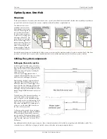
The 14 bit D/A samples are stored in twos complement in the lower 14 bit of the 16 bit data word. 14 bit resolution means that data is
ranging from -8192…to…+8191. In standard mode the upper two bits contain the sign extension allowing to directly use 16 bit integer
values for the write data directly. If digital outputs are activated these outputs are stored in the two upper bits.
Hardware data conversion
The data conversion modes allow the conversion of input data in hardware. This is especially usefull when replaying previously recorded
data of acquisition cards with either a higher 16bit or lower 12bit resolution. The conversion takes place in hardware and therefore avoids
a possible time consuming shift in the user application software.
The data conversion modes require driver version V2.11 (or newer) and firmware version V18 (or newer).
Please update your system to the newest versions to use this mode.
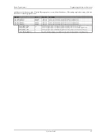
To enable the generation of the digital outputs you simply have to set the according register shown in the table below.
Due to technical issues there is a board dependant fixed delay between the analog and digital samples.
Electrical specifications
The electrical specifications of the digital inputs option can be found either in the technical data section of this manual or in the datasheet.
Programming the behavior after output
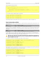
Usually the corresponding digital outputs of the analog generation boards are set to LOW level after replay. This is in most cases adequate.
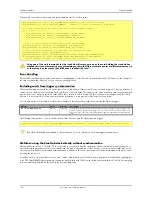
In some cases it can be necessary to hold the last sample, or to output a HIGH level after replay. The stoplevel will stay on the defined level
Bit
Standard Mode
Digital outputs (option)
enabled
D15
DAx Bit 13
Digital bit 1 of channel x
D14
DAx Bit 13
Digital bit 0 of channel x
D13
DAx Bit 13 (MSB)
DAx Bit 13 (MSB)
D12
DAx Bit 12
DAx Bit 12
D11
DAx Bit 11
DAx Bit 11
D10
DAx Bit 10
DAx Bit 10
D9
DAx Bit 9
DAx Bit 9
D8
DAx Bit 8
DAx Bit 8
D7
DAx Bit 7
DAx Bit 7
D6
DAx Bit 6
DAx Bit 6
D5
DAx Bit 5
DAx Bit 5
D4
DAx Bit 4
DAx Bit 4
D3
DAx Bit 3
DAx Bit 3
D2
DAx Bit 2
DAx Bit 2
D1
DAx Bit 1
DAx Bit 1
D0
DAx Bit 0 (LSB)
DAx Bit 0 (LSB)
Register
Value
Direction
Description
SPC_AVAILDATACONVERSION
201401
read
Bitmask, in which all bits of the below mentioned data conversion modes are set, if available.
SPC_DATACONVERSION
201400
read/write
Defines the used hardware data conversion mode or reads out the actual selected one.
SPCM_DC_NONE
0h
No hardware data conversion will be done.
SPCM_DC_12BIT_TO_14BIT
1h
12bit input data is assumed and samples will be logically shifted upwards to use available 14bit resolution.
SPCM_DC_16BIT_TO_14BIT
2h
16bit input data is assumed and samples will be arithmetically shifted downwards to use available 14bit resolution.
Register
Value
Direction
Description
SPC_PATTERNENABLE
110000
r/w
Writing a „1“ enables, writing a „0“ disables the generation on all of the installed digital outputs.
This is only possible if the option “digital outputs“ is installed on the board.


