


MiniCapt® Mobile Operations Manual
8-1
Chapter 8
Warnings and Alarms Setup
This chapter describes configuration of warnings and alarms for the MiniCapt Mobile
Microbial Air Sampler.
Warnings:
A warning will occur if the flow is ± 5% of the calibrated flowrate (up to ±20%).
The warning will be visual on the screen as well as audible if sound is configured.
See
Alarms:
An alarm will occur if the flow is outside of 20% of the calibrated flowrate.
The alarm will be visual on the screen as well as audible if selected and the MiniCapt
will turn off.
An alarm comment will need to be entered using the drop down menu.
See
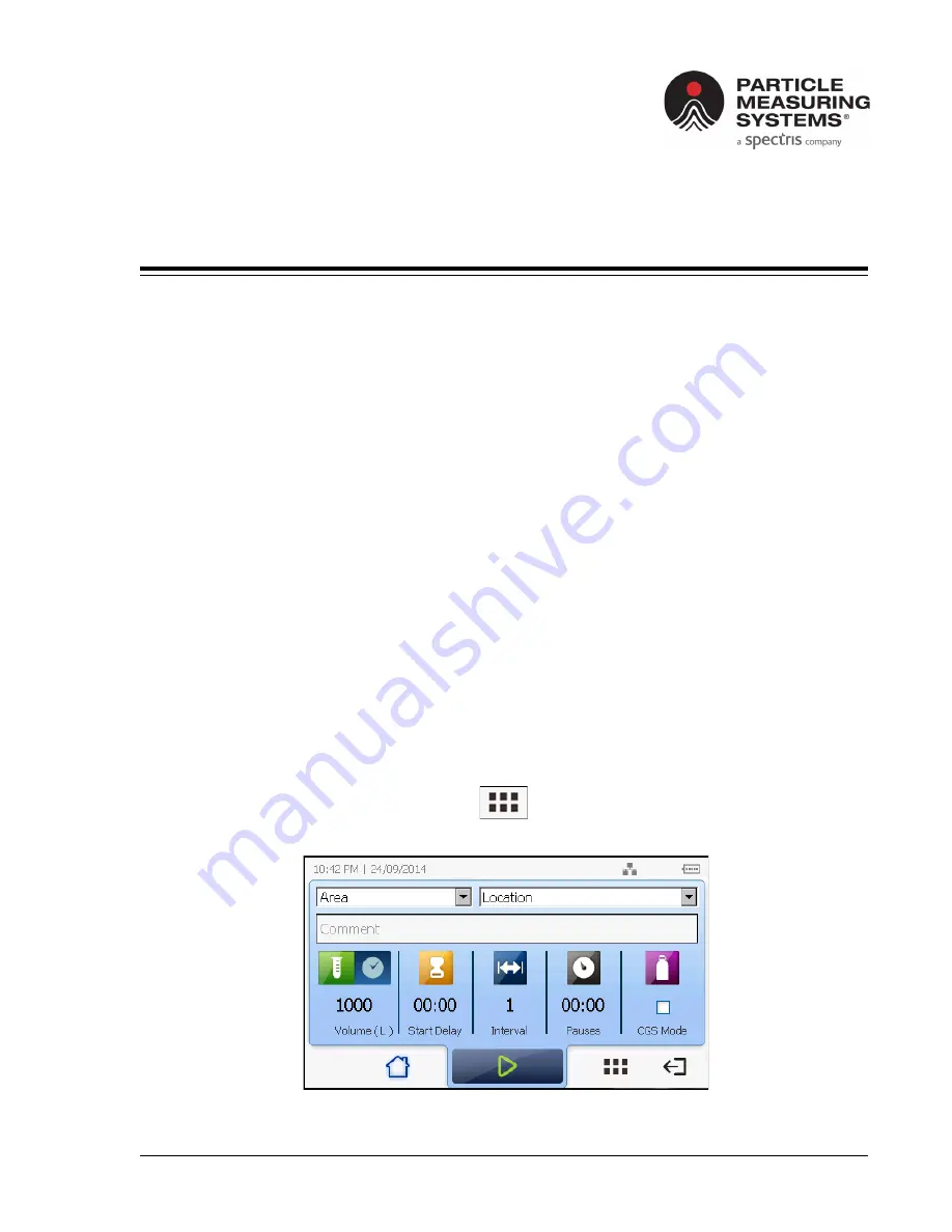
View the Warnings and Alarms List Screen
>> To view the Warnings and Alarms List screen:
1.
On the
Home
screen, touch
the
Features Menu
button (see
).
The
Features Menu
screen appears (see
Figure 8-1 Home
screen
Содержание PARTICLE MEASURING SYSTEMS MiniCapt
Страница 13: ...xii MiniCapt Mobile Operations Manual Table of Contents This page is intentionally left blank ...
Страница 81: ...5 10 MiniCapt Mobile Operations Manual Chapter 5 Recipes Delete a Recipe This page is intentionally left blank ...
Страница 197: ...C 2 MiniCapt Mobile Operations Manual Appendix C 有毒或有害的物质和元素 This page is intentionally left blank ...


