background image

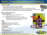
Powering the SF601

1. Open the battery door pulling the battery door latch.

The SF601will be shipped with alkaline batteries.

Rechargeable batteries can be used optional but need to be charged externally

2.  Insert four AA batteries noting the plus (+) and minus (-) diagrams inside on the battery door.
3. Close the battery door. Push down until it “clicks” into the locked position. 

SF601 - Features and Functions

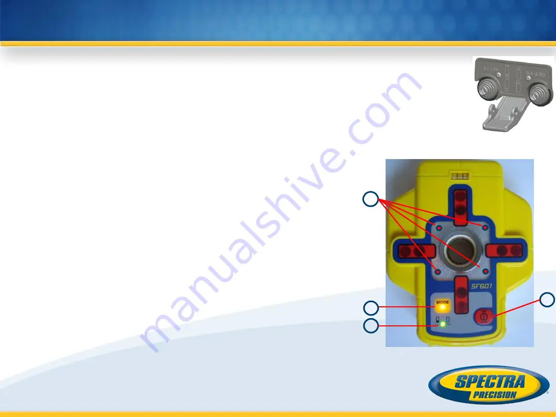
1. Power/Mode Button:

Press and release the power button to turn ON the SF601.

All display LED’s will light for 1.0 sec.

Press and hold power button  for >1 sec. to turn OFF the SF601. 

Note: 

If the SF601 has been turned on, a short button press 

activates/deactivates the fan beam lens (a previously chosen 
automatic mode will be exited automatically). 

LED’s:

2. LED1: 

solid green 

when SF601 is on and battery OK

blinking red 

if battery voltage is 3,8V<V bat <4V

solid red 

if battery voltage is <3,8V; SF601 turns off 

automatically after 5 min. 

3.  Mode LED2:

yellow solid: 

automatic mode

flashing: 

none or lost signal

off: 

manual mode 

4. Direction LEDs red:

Manual mode: 

pointing towards the center of the plumb beam. 

All 4 LEDs are solid red when the beam is centered.

Automatic Spot Lock mode: 

solid for 5 min., then LED’s flash every 5 seconds.

SF601 

– Powering/Features and Functions

1

2

3

4

Содержание Trimble UL 633N

Страница 1: ...UL633N Hands On training 11 07 17...

Страница 2: ...pad LCD Display b Handle c Rotor with fan beam lens d Sunshade e Axes Alignment Marks f Sighting Guides Scope Mounts g Battery door h Rubber Cover Recharge Jack i 5 8 x 11 Tripod Mounts j Rubber Feet...

Страница 3: ...e rechargeable battery pack can be charged inside as well as outside of the unit 3 The charger Q104781 can be used as a power supply when used Indoors 4 Alkaline batteries can be used as a backup 5 An...

Страница 4: ...tab on the RC603N RC603N will be shipped with alkaline batteries Rechargeable batteries can be used optional but need to be charged externally 2 Insert two AA batteries noting the plus and minus diagr...

Страница 5: ...grade entering mode Button 3 Quickly press and release activates deactivates the manual mode Button 4 Quickly press and release to toggle through the pre selected rotation speeds Press and hold for th...

Страница 6: ...check the leveling time can be increased When the temperature reference check has been finished the standard display appears and the bubble symbols flash until self leveling has been completed Don t s...

Страница 7: ...ont of the comma will be set to 0 and then starts changing in 1 increments Press and hold button 5 or 8 up down for changing Y Z axis grade value press and hold buttons 5 8 simultaneously starts Y Z a...

Страница 8: ...e value and return to the standard display Press and release button 5 or 8 down or up to move the cursor to the X or Y axis not used in Z mode Pressing and releasing button 6 or 7 right or left moves...

Страница 9: ...Press and hold button 4 at the Standard Display for three seconds to change the unit into scan mode Quickly press and release button 4 to toggle between the pre selected scan sizes 5 15 45 90 180 degr...

Страница 10: ...al In Manual mode horizontal the Y axis can be sloped by pressing the Up 5 and Down 8 Arrow buttons on the laser s keypad or the remote control Additionally the X axis can be sloped by pressing the Le...

Страница 11: ...arrow at the the right site indicates that the user can scroll up down through the menu rows 4 different screens using the buttons 5 8 up down arrows Pressing and releasing button 3 changes the unit...

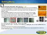
Страница 12: ...already paired remote with a new transmitter The new transmitter has to be set to the pairing dialog for this operation Otherwise the pairing can not be successful processed The pairing information o...

Страница 13: ...ver should be permanently mounted at this location and at the desired elevation 3 Use the sighting guides on the top of the laser to align the laser to the receiver Turn the laser on the tripod until...

Страница 14: ...at the HL760 display Note The laser continues to servo to the receiver s signals 6 Exiting of PlaneLok can be done by pressing button 3 ESC Note If the setup will be disturbed for a minute beam will b...

Страница 15: ...he steep slope area using the slope bracket M402 laser tilting base Check the laser beam elevation and place the two receivers at the desired hubs Change the UL into manual mode and tilt the unit to t...

Страница 16: ...017 16 Steep Slope using PlaneLok Select PlaneLok at the menu and start Dual Axis PlaneLok by pressing button 4 The transmitter starts searching for both receivers and locks the beam at the on grade p...

Страница 17: ...ange on both axes is 40 4 Press and release the MENU button at the Standard Display and select Grade Match 5 Select the desired Grade Match axis then press button 4 to start Grade Match Note The laser...

Страница 18: ...start manual Grade Match The grade for the Y axis can be adjusted with button 5 8 while button 6 7 adjust the X axis During Manual Grade Match a crossed vial and angle symbol appear next to the conti...

Страница 19: ...urn the laser on the tripod until it is roughly aligned to the receiver s position the alignment range on both axes is 40 4 Press and release the MENU button at the Standard Display and select Axis Al...

Страница 20: ...ment to the second direction point 5 After repeating step 2 and 3 the display shows the new alignment angle and the angle difference between the two direction points Edit Align Angles Selecting Edit A...

Страница 21: ...8 to move the flashing bar to other required areas and repeat the setting process When all areas have been set press button 4 to store the mask sector selection until the unit will be turned off Note...

Страница 22: ...starts the reference check considering the current temperature inside the housing While the procedure the rotation will be stopped Note A grade value has to be entered before the unit starts the refer...

Страница 23: ...Buttons 6 7 can be used to toggle between UL RC and Runtime Press and release button 4 to confirm the selection The UL RC information software version ID etc or the runtime of the UL will be displayed...

Страница 24: ...n procedure The RC603N Service menu offers additional features RF IR options Press and release button 4 to confirm the selection and select one of the following options RF On IR auto Radio on all time...

Страница 25: ...button 4 activates the fan beam while the rotation speed changes to 750 rpm and the unit goes back to the standard display The 4 red LEDs around the center hole guide the user to the plumb beam s cent...

Страница 26: ...4 Press and release the MENU button at the Standard Display and select Spot Align 5 Pressing and releasing button 4 starts the automatic spot alignment while the plumb beam becomes a rotating fan beam...

Страница 27: ...at the second reference point 3 Press and release the MENU button at the Standard Display and select SpotLok 4 Pressing and releasing button 4 starts the automatic spot alignment while the plumb beam...

Страница 28: ...t end of the trench 3 Press and release the MENU button at the Standard Display and select Spot Match 4 Pressing and releasing button 4 starts the automatic spot alignment while the plumb beam becomes...

Страница 29: ...the manual button 3 to change the unit back to full automatic mode Beam Plunge Beam Plunge centers the rotor vertically and can be used to align the plumb beam to a desired vertical position e g when...

Страница 30: ...using button 1 CLR 3 Turn on the RC603N and select the Pairing menu and press button 4 The UL633N pairs now automatically with the new remote control Setting Menu Pairing Grade Entry Display Sensitivi...

Страница 31: ...display shows MENU first then RDIO Press and release the Units C button display shows the current radio mode If not already set to LS press Units button C and then press Deadband or Audio button unti...

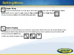
Страница 32: ...d Go and Digit Select Press and release button 4 to confirm the selection Grade Display Select the Grade Display icon and press and release button 4 to open the Grade Display menu The desired Grade Di...

Страница 33: ...ected using the buttons 6 7 Press and release button 4 to confirm the selected HI alert User Name Select the User name icon and press and release button 4 to open the User name menu Cursor flashes One...

Страница 34: ...urns off automatically Password On Off Select the Set Password ON Off icon and press and release button 4 to open the Password menu Buttons 6 7 can be used to toggle between Password On and Password O...

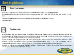
Страница 35: ...s caused by different gravity The user has the chance to provide the position info of the job site to the product This is the degree of latitude as well as the altitude Chose Settings and navigate to...

Страница 36: ...er not available for single axis automatic function Make sure the receiver is on and paired 151 No receivers Both receivers are not available for automatic alignment function Make sure both receivers...

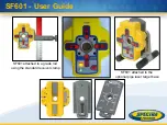
Страница 37: ...SF601 User Guide SF601 attached to a grade rod using the standard receiver clamp SF601 attached to the optional pipe laser target base...

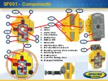
Страница 38: ...al 6 Battery LED 7 Mode LED 8 Red Direction LEDs 9 IR transmitters receivers 10 Marking notches front and back 11 M6 Clamp Mount 12 Battery door 13 Latch for Battery Door 14 Release Tab Slider SF601 C...

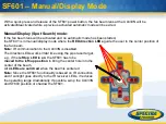
Страница 39: ...power button for 1 sec to turn OFF the SF601 Note If the SF601 has been turned on a short button press activates deactivates the fan beam lens a previously chosen automatic mode will be exited automat...

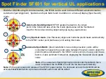
Страница 40: ...int both axes until exiting this mode Automatic Spot Match like Grade Match two existing elevation points will be connected to measure the grade value between these two points aligns the plumb beam au...

Страница 41: ...er position of the fan beam Note IR communication to the UL633N is disabled The direction LEDs work similar like using the pipe laser target e g if the left top LED is on the SF601 has to be moved to...

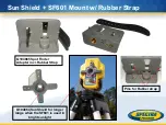
Страница 42: ...Sun Shield SF601 Mount w Rubber Strap Pins for Rubber strap Q104864 Sun Shield for longer range when the SF601 is used in bright sunlight Q104865 Spot Finder Adaptor incl Rubber Strap...

Страница 43: ...Q104865 Mount SF601 Tripod Setup Tripod thread centered with the SF601 and tripod mounting threads...

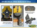
Страница 44: ...Q104865 Mount SF601 Batter Board Setup Marking notch aligned with the center of the nail Clamp thread for attaching the receiver clamp...

Страница 45: ...Q104865 Mount SF601 Free Standing Setup Marking notches on both sites...

Отзывы: