background image

52

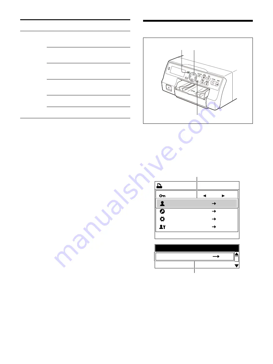
Basic Menu Operations

1

Press the MENU button.

The [Printer Menu] screen appears.

2

Press the 

 or 

 button to select the desired 

menu.

Example: Selecting the [User Setup] menu

3

Press the 

 button.

The [User Setup] screen appears.

Machine 

Setup

Setting the message display 

language (Message 

Language)

24

Setting whether or not to 

allow operation sounds and 

alarms (Beep)

73

Adjusting the contrast of the 

printer window display (LCD 

Contrast)

73

Adjusting the brightness of 

the printer window display 

(LCD Backlight)

73

Setting the tray light function 

(Tray Light)

73

Setting the tray light 

brightness (Tray Light Level)

73

Tab

Functions that can be set

Reference 

page

1

2, 3, 4, 5, 6

EXEC button

End : MENU

Printer Menu

Lock

User Setup

System Setup

Maintenance

Service

User Setup

Printer Menu

System Setup

Use the 

 or 

 button to move the cursor box to [User Setup].

Use the 

 or 

 button to highlight [User Setup].

Содержание UP-27MD

Страница 1: ...Color Video Printer Instructions for Use Before operating the unit please read this manual thoroughly and retain it for future reference UP 27MD 5 029 577 11 1 2021 09 2021 Sony Corporation ...

Страница 2: ...nsating for source image brightness etc 55 Matching the video monitor and printout color 56 Adjusting the printout sharpness 58 When a black frame or lines show up on printouts 59 Printing to match paper size 60 Adjusting the color balance 61 Specifying colors for adjustment 64 Setting the HD signal aspect ratio 69 Configuring Various Settings 69 Registering a user settings 69 Returning user setti...

Страница 3: ... operation of the unit operate the disconnect device to switch the power supply off or disconnect the power plug Warning Symbols on the product Consult the instructions for use Follow the directions in the instructions for use for parts of the unit on which this symbol appears This symbol indicates the manufacturer and appears next to the manufacturer s name and address This symbol indicates the I...

Страница 4: ...in the medical environments 1 All devices connected to the unit must be certified or compliant according to IEC 60601 1 IEC 60950 1 and IEC 60065 standards and other IEC ISO standards applicable to the devices 2 Furthermore the system as a whole must comply with IEC 60601 1 standards All peripheral devices connected to the signal input output sections of the unit constitute the medical use system ...

Страница 5: ...specified with the exception of replacement parts sold by Sony Corporation may result in increased emissions or decreased immunity of the UP 27MD Guidance and manufacturer s declaration electromagnetic emissions The UP 27MD is intended for use in the electromagnetic environment specified below The customer or the user of the UP 27MD should assure that it is used in such an environment Emission tes...

Страница 6: ...de 2 kV common mode Mains power quality should be that of a typical commercial or hospital environment Voltage dips short interruptions and voltage variations on power supply input lines IEC 61000 4 11 0 UT 100 dip in UT for 0 5 1 cycles a 70 UT 30 dip in UT for 25 30 cycles a for 0 5 sec 0 UT 100 dip in UT for 250 300 cycles a for 5 sec 0 UT 100 dip in UT for 0 5 1 cycles a 70 UT 30 dip in UT for...

Страница 7: ...0 4 6 3 Vrms 150 kHz to 80 MHz outside ISM bands c 3 Vrms d 1 2 P 6 Vrms 150 kHz to 80 MHz in ISM bands c 6 Vrms Radiated RF IEC 61000 4 3 3 V m 80 MHz to 2 7 GHz 3 V m d 2 0 P 80 MHz to 2 7 GHz Where P is the maximum output power rating of the transmitter in watts W according to the transmitter manufacturer and d is the recommended separation distance in meters m Field strengths from fixed RF tra...

Страница 8: ...s equipment and the UP 27MD The UP 27MD is intended for use in an electromagnetic environment in which radiated RF disturbances are controlled The customer or the user of the UP 27MD can help prevent electromagnetic interference by maintaining a minimum distance between portable and mobile RF communications equipment transmitters and the UP 27MD as recommended below according to the maximum output...

Страница 9: ...should be used no closer than 30 cm 12 inches to any part of the UP 27MD Otherwise degradation of the performance of this equipment could result Immunity test Band a Service a Modulation IEC 60601 test level Compliance level Proximity fields from RF wireless communications equipment IEC 61000 4 3 380 390 MHz TETRA 400 Pulse modulation 18 Hz 27 V m 27 V m 430 470 MHz GMRS 460 FRS 460 FM 5 kHz devia...

Страница 10: ...RANTY Please visit http www sony com psa warranty for important information and complete terms and conditions of Sony s limited warranty applicable to this product For the customers in Canada SONY LIMITED WARRANTY Please visit http www sonybiz ca pro lang en ca article resources warranty for important information and complete terms and conditions of Sony s limited warranty applicable to this produ...

Страница 11: ...G signal input output support SD 1080i and 1080p signal formats are supported Signal formats are automatically detected via settings High definition display window A high definition display window on the front panel makes it easy to check the printer status and use the menu Part Names and Functions Front PRINT indicator Lights while printing is in progress ALARM indicator Lights when an error such...

Страница 12: ...ton page 27 Repeatedly press this button to set the print quantity You can select up to nine copies and the current selection is displayed for a few seconds when the button is pressed Print Quantity in the Print Setup tab of the User Setup menu also changes in conjunction with each press of this button CAPTURE button Capture images to memory for printing PRINT button Print the images that are capt...

Страница 13: ...d disconnecting connectors REMOTE connector stereo mini jack page 16 Connects to an FS 24 Foot Switch not supplied RS 232C connector page 16 Connects to a computer for controlling the printer Caution Do not come into contact with this terminal and patients at the same time Doing so may result in a generation of voltage that can be harmful to patients if the unit is malfunctioning Always disconnect...

Страница 14: ...he printer monitor display only Captions Displays whether or not to the printer is set to add a caption to the print Monitor display On Adds a caption Off Does not add a caption Printer window display is displayed when the printer is set to add a caption Reduced image setting Monitor display Displays the number of reduced image screens Printer window display Displays the type of reduced image scre...

Страница 15: ...connectors on this unit are not isolated Do not connect any device other than one which conforms to IEC 60601 1 standards When an information technology device or AV device that uses an alternating current is connected current leakage may result in an electric shock to the patient or operator If use of such a device is unavoidable isolate its power supply by connecting an isolation transformer or ...

Страница 16: ...pplied or a computer To video input connector Video monitor 75 coaxial cable with BNC connector 5C FB or equivalent Power cord To AC power source To AC IN To 3G SDI HD SD output Computer a To RS 232C To AC power source RS 232C cable Power cord To REMOTE To AC IN a When controlling the printer from a computer set the appropriate baud rate See Setting the communication speed with a printer page 73 F...

Страница 17: ...es the dyes used in this ink ribbon may discolor over time the product will neither be replaced nor be warranted against any color change Do not replace the ink ribbon and paper roll when they are only partially used Doing so can cause problems The number of printouts indicated above is not guaranteed Storing paper Avoid storing paper in a location subject to high temperatures and humidity excessi...

Страница 18: ...n the ribbon door panel 2 Pull the ribbon tray straight out of the printer 3 Load the ink ribbon Align the two pegs on each side of the ink ribbon with the slots on the ribbon tray Notes Make sure to load the ink ribbon with the front and back oriented correctly Before loading the ink ribbon make sure to position the start mark as shown in the illustration and remove any slack by turning the gear ...

Страница 19: ...n tray To remove the ribbon tray when replacing the ink ribbon for example pull the tray straight out If the ink ribbon tears during use Cellophane tape etc can be used to repair a torn ink ribbon so that the remainder of the ribbon can be used Wind the ink ribbon until the cellophane tape is no longer visible by turning the black or gray gear at the winding end in the direction of the arrow Make ...

Страница 20: ...ful when inserting and removing the paper feed tray because it may cause the printer to shift position and fall When the paper runs out do not just add more paper When the paper runs out replace both the paper and the ink ribbon Replenishing the paper midway may cause a paper jam 1 Press the mark on the paper feed tray to eject the tray 2 Open the lid of the paper feed tray and load the paper and ...

Страница 21: ...ed tray 3 Remove the protective sheet and close the lid Note Make sure to keep the protective sheet after removing it The reverse side of the protective sheet without printing can be used as a cleaning sheet to clean the thermal head For details see Cleaning the thermal head page 76 4 Insert the paper feed tray into the printer until it clicks into place Notes If the paper feed tray cannot be comp...

Страница 22: ...onnectors on the rear of the printer Note When settings are changed it may take several seconds to switch Capturing is not available during switching 1 Turn on the video monitor and the printer 2 Press the MENU button use the or button to select the System Setup menu and then press the button The System Setup screen appears 1 2 5 2 3 4 End MENU Printer Menu Lock 2ı User Setup System Setup Maintena...

Страница 23: ... 1 3G SMPTE ST 424 For information on the relation between the input signal format and output signal see Input signal format and output signal relation page 80 Option Description Auto default value Automatically detects the input signal format For details see Supported signal formats page 23 1080p Locks the source image to 1080p 1080i Locks the source image to 1080i SD Locks the source image to SD...

Страница 24: ...the and buttons to choose the language 4 Press the MENU button The System Setup screen is closed 1 4 1 2 3 End MENU Printer Menu Lock 2ı User Setup System Setup Maintenance Option Description Monitor display Printer window display English default value E default value English Japanese J Japanese End MENU Machine Setup Message Language System Setup Beep LCD Contrast LCD Backlight Tray Light Tray Li...

Страница 25: ...e controls of the connected video equipment 3 Press the CAPTURE button at the instant the image appears on the screen The image is captured into memory The memory image is displayed on the video monitor You can select the mode for automatically switching source images to show on the video monitor For details see Setting the image displayed on the video monitor after capture page 32 To change the i...

Страница 26: ...se information and messages displayed on the screen so you can view a hidden image press the DISPLAY button See Hiding the Screen Display on the Video Monitor page 46 You can also erase the ink ribbon type and remaining print information See Displaying the ink ribbon or printer setting information page 71 If a black frame or line appears on the printout Sometimes a black frame or line appears on t...

Страница 27: ...he user setting 3 Press the EXEC button The printer switches to the user setting specifications selected in step 2 and the user settings selected on the printer window display appear 4 Press the CAPTURE button at the instant the image appears on the screen The image is captured into memory according to the user setting selected in step 2 5 Press the PRINT button The printer makes printouts accordi...

Страница 28: ...ing to the operations of step 1 described in Making printouts with a user registered settings page 27 2 Use the or button to select the Print Setup tab then the or button to select Print Quantity 3 Use the or button to set the print quantity 4 Press the MENU button The User Setup screen is closed 2 1 2 Currently selected number of copies Print Quantity 1 Print Quantity 3 Set print quantity Button ...

Страница 29: ...ress the PRINT button again If you want to print the remaining printouts reset the print quantity Queuing another image while printing While the printing you can queue printing jobs by capturing another image into another memory page The number of usable memory pages depend on the type of printouts and settings See Memory page page 30 1 Repeatedly press the MEMORY PAGE button to select a memory pa...

Страница 30: ... differs depending on the printing pack used Selecting a memory page Memory page A memory area in which an image is captured is called a memory page in this manual The number of usable memory pages depends on the type of the reduced images selected and on the connected equipment Note Images of differing signal types HD SD 480i or SD 576i cannot coexist on the same multiple reduced image screen If ...

Страница 31: ...f reduced images Determine the number of reduced images page 31 Select the memory page page 30 Selecting the number of reduced images to be captured in memory The following methods are available to select the number of reduced images Using the MULTI PICTURE button Using the menu To make a selection using the MULTI PICTURE button 1 Press the MULTI PICTURE button The Multi Picture screen appears for...

Страница 32: ...he image displayed on the video monitor as a source image or set a memory image 1 Display the User Setup screen according to the operations of step 1 described in Making printouts with a user registered settings page 27 Type Number of reduced images names in parentheses are used in this manual 1 default value One Full size image 2 Two Two reduced images 4 Four Four reduced images End MENU Printer ...

Страница 33: ... layout to four reduced images page 31 Select the appropriate memory page page 30 Select which image will appear after the image has been captured into memory page 32 Select whether to add white frames page 34 The white border setting for printouts of four reduced images can be made before or after the four images are captured to memory Option Description On Displays the image captured in memory t...

Страница 34: ...ace a captured image Example When you want to change the image captured in the third position Use the or button to select the image in the third position Display the source image on the video monitor For further details see step 3 Press the CAPTURE button The previously captured image is replaced with the newly captured image To keep a previously captured image Skip images that you want to keep by...

Страница 35: ...s the MENU button The User Setup screen is closed Option Description On default value Print images with white frames Off Print images without white frames End MENU Load User Setup Multi Picture User Setup Function Setup Output Setup Print Setup White Frames Caption Caption Edit Color Tone Print Quantity Print Speed 1 On 2ı 1 High End MENU Load User Setup Multi Picture User Setup Function Setup Out...

Страница 36: ...m x c z v Space 1 2 1 3 2 Text input display area Text input with the keyboard is displayed at the cursor position Keyboard EXIT After entry is complete return to the Print Setup screen 1 2 3 4 5 6 7 8 9 0 w q e r t y u i o p 1 2 3 Text input display area When 58 characters are entered the text is displayed in four lines One line with the cursor is also displayed Keyboard Key Description B S Delet...

Страница 37: ...ps then press the EXEC button When entering uppercase letters the selection changes to lowercase letter input When entering lowercase letters the selection changes to uppercase letter input Note The text already entered in the text input display area will not change To delete character Use the or button to select B S then press the EXEC button Each time the EXEC button is pressed a single characte...

Страница 38: ...n a single sheet You can also zoom part of the image such as text information from the top left of the four reduced images to create reduced images Tip The zoom function is only available when the reduced images is set to four reduced images and using an HD video signal input The following modes are available when zooming Zoom Mode Part The fixed area is zoomed on the first screen and the image ar...

Страница 39: ... described in Making printouts with a user registered settings page 27 2 Use the or button to select the Print Area Setup tab then the or button to select Zoom Mode 3 Use the or button to select the zooming method 123456789 ABCDEFGH abcdefghij 123456789 ABCDEFGH abcdefghij 123456789 ABCDEFGH abcdefghij 123456789 ABCDEFGH abcdefghij Image area Option Description Off default value Creates a regular ...

Страница 40: ...d captured in all pages regardless of the number of captures or pages 6 Press the PRINT button The printouts are created All Zooms and prints image area images in all screens Option Description 123456789 ABCDEFGH abcdefghij 123456789 ABCDEFGH abcdefghij 123456789 ABCDEFGH abcdefghij 123456789 ABCDEFGH abcdefghij 123456789 ABCDEFGH abcdefghij 123456789 ABCDEFGH abcdefghij 123456789 ABCDEFGH abcdefg...

Страница 41: ...r Setup Zoom Mode Zoom Area Zoom Position Zoom Range Small Zoom Range Large Part Small Upper Left V Start V Width H Start H Width 123456789 ABCDEFGH 123456789 ABCDEFGH abcdefghi 123456789 ABCDEFGH 123456789 Setting item Setting range default value Description H Start 16 9 16 10 240 to 1000 636 Sets the image capture position left edge in the horizontal direction for an aspect ratio of 16 9 or 16 1...

Страница 42: ...p edge in the vertical direction for an aspect ratio of 16 10 H Start 4 3 5 4 0 to 1000 240 Sets the image capture position left edge in the horizontal direction for an aspect ratio of 4 3 or 5 4 Setting item Setting range default value Description End MENU Zoom Range Large H Start 16 9 V Start 16 9 H Start 16 10 V Start 16 10 H Start 4 3 5 4 V Start 4 3 5 4 H Width L Back 480 0 384 0 240 0 1440 H...

Страница 43: ...etween images captured in memory when reduced images in memory are deleted The function for the STOP CLEAR button is set in Clear Button on the Function Setup tab of the User Setup menu Because the STOP CLEAR button functions as the STOP button when printing is in progress images cannot be deleted while printing is in progress Setting the function of the STOP CLEAR button 1 Display the Function Se...

Страница 44: ...ou cannot restore images once they have been deleted To delete images in all memory pages Check Using Clear Button in the Function Setup tab of the User Setup menu set the STOP CLEAR button function to All Images Press the STOP CLEAR button All images captured in the printer are cleared Option Description All Images default value Deletes images in all memory pages simultaneously Selected Page Dele...

Страница 45: ...or 2 Select the memory page from which images are to be deleted by pressing the MEMORY PAGE button 3 Press the STOP CLEAR button The images in the memory page selected in step 2 are deleted To delete a single reduced image Check Using Clear Button in the Function Setup tab of the User Setup menu set the STOP CLEAR button function to Selected Part For setting instructions see Setting the function o...

Страница 46: ...If you press the DISPLAY button while the information in step 1 is displayed Off appears Each time you press the DISPLAY button the setting switches between All Ribbon Off To restore the screen display Press the DISPLAY button and select All or Ribbon To set the screen display from the menu screen In Information Display on the Output Setup tab of the User Setup menu you can hide setting informatio...

Страница 47: ... controls When turned On a lock icon appears on the printer window display 3 Press the MENU button The Printer Menu screen is closed When turned On only the Lock menu is enabled and all other items are unavailable Note Even if controls are locked they will be released when the printer is set to TRANSPORT MODE Option Description On Locks printer button controls Off default value Allows printer butt...

Страница 48: ...ta Green Yellow Blue Message Language Beep LCD Contrast LCD Backlight Tray Light Tray Light Level Print Parameters All Reset Roller Cleaning Head Cleaning Notify Capture Print C Print Cyclic C Cap Stop Back SP Pointer Stop Cap Src Cap S Page Print Page Src Cap Src C Page 1200 2400 4800 9600 Bal X Bal Y Bal Step Test Print Color Sel Intensity Saturation Value Hue Split9 Step Test Print 16 9 16 10 4...

Страница 49: ...an Red Magenta Green Yellow Blue Dark Light Sharpness Gamma 1 9 Normal High Aspect Ratio H Start V Start H Width V Width Resize To Fit H Start 16 9 16 10 V Start 16 9 16 10 H Start 4 3 5 4 V Start 4 3 5 4 H Width S V Width S H Start 16 9 V Start 16 9 H Start 16 10 V Start 16 10 H Start 4 3 5 4 V Start 4 3 5 4 H Width L V Width L User 01 User 02 User 03 User 04 User 05 User 06 User 07 User 08 User ...

Страница 50: ...o 16 10 H Start V Start H Width V Width 0 72 0 48 560 720 400 480 H Start V Start H Width V Width 0 72 0 48 560 720 496 576 H Start V Start H Width V Width 0 240 960 0 540 720 1440 540 1080 H Start V Start H Width V Width 0 320 960 0 27 540 720 1280 1440 540 1026 1080 H Start V Start H Width V Width 0 960 0 540 960 1920 540 1080 H Start V Start H Width V Width 0 96 960 0 540 960 1728 1920 540 1080...

Страница 51: ...Selecting the type of printout Multi Picture 31 Selecting whether or not white frames are added to multiple reduced images White Frames 34 Entering a caption Caption Caption Edit 36 Adjusting the printout color contrast sharpness and tone Color Tone 58 Setting the print quantity Print Quantity 28 Selecting the print speed Print Speed 26 Print Area Setup Adjusting the printed image area to eliminat...

Страница 52: ... and alarms Beep 73 Adjusting the contrast of the printer window display LCD Contrast 73 Adjusting the brightness of the printer window display LCD Backlight 73 Setting the tray light function Tray Light 73 Setting the tray light brightness Tray Light Level 73 Tab Functions that can be set Reference page 1 2 3 4 5 6 EXEC button End MENU Printer Menu Lock 2ı User Setup System Setup Maintenance Serv...

Страница 53: ...tion Edit Color Tone Print Quantity Print Speed 1 On 2ı 1 High Print Area Setup User Setup Print Setup Use the or button to highlight the Print Setup tab Use the or button to display the Print Setup tab End MENU Load User Setup Multi Picture User Setup Function Setup Output Setup Print Setup White Frames Caption Caption Edit Color Tone Print Quantity Print Speed 1 On 2ı 1 High Print Speed Print Se...

Страница 54: ...he button End MENU Load User Setup Multi Picture User Setup Function Setup Output Setup Print Setup White Frames Caption Caption Edit Color Tone Print Quantity Print Speed 1 On 2ı 1 Normal Print Speed Print Setup Normal Use the or button to display Normal Use the or button to display Normal End MENU Remote Setup Cyan Red System Setup Color Correction Input Setup Monitor Color Tone Magenta Green Ye...

Страница 55: ...ure the image to memory after compensation is complete Check When the memory image is displayed on the video monitor press the SOURCE MEMORY button to display the image from the video source 1 Display the Input Setup tab of the System Setup screen use the or button to select Video Adjustment then press the button The Video Adjustment screen appears End MENU Color Tone Cyan Red Magenta Green Yellow...

Страница 56: ... monitor adjust the printer color Printer adjustment Note This adjustment is performed to adjust the printer video monitor output when it does not match the printout color This adjustment does not affect the printout To adjust the sharpness of the printout see Adjusting the color contrast and sharpness page 58 and Specifying colors for adjustment page 64 Setting item Setting range default value De...

Страница 57: ...urce image color EE signal Through Outputs to the video monitor without compensating the source image color Through signal End MENU Load User Setup Information Display User Setup Function Setup Output Setup Print Setup Messages Display Source Image All On General Setting item Setting range default value Description Cyan Red 14 to 14 0 Press the button to make the image cyan light blue Press the bu...

Страница 58: ...nt Setup White Frames Caption Caption Edit Color Tone Print Quantity Print Speed 1 On 2ı 3 High End MENU Color Tone Cyan Red Magenta Green Yellow Blue Dark Light Sharpness Gamma Back 0 0 0 0 0 8 Normal Select the desired item then perform the adjustment Setting item Setting range default value Description Cyan Red 7 to 7 0 Press the button to make the image cyan light blue Press the button to make...

Страница 59: ...b of User Setup screen use the or button to select General Range then press the button The General Range screen appears 2 Adjust the captured image position according to the printout The selected range of the setting value may differ depending on the aspect ratio of the input signal Option Description Soft Select this to make a printout of a source image with a lot of white areas soft tone Normal ...

Страница 60: ...o reset the vertical settings to factory default values position the cursor at either V Start or V Width then press the and buttons simultaneously To reset the horizontal settings to factory default values position the cursor at either H Start or H Width then press the and buttons simultaneously To check the adjustment result Print to check that no black frame appears on the printout that the imag...

Страница 61: ... the System Setup screen use the or button to select Color Balance then press the button The Color Balance screen appears The highlighted area on the screen will be printed to be used for adjusting the color balance You can move this area Note If the layout was set to two or four reduced image display the page on which the pointer was positioned will be displayed at full size image When you adjust...

Страница 62: ...nt color balance This print operation can also be performed by pressing the PRINT button while the Color Balance screen is displayed Color changes in the test print are as follows 5 Select the image which has the best color balance from the printed results If you want to change the color balance after you see the printout adjust the color balance again referring to To readjust the color balance pa...

Страница 63: ...e from the printed images using the or button In this case you can either fine tune or make coarse adjustments by changing the value of Bal Step To make fine tune adjustments To fine tune the color balance within the current range reduce the current Bal Step value Setting item Setting range default value Description Bal X 1 to 99 50 Adjusts the X axis green red color balance Bal Y 1 to 99 50 Adjus...

Страница 64: ... adjustments are captured to memory Before performing HSV adjustment In the Monitor Color Tone tab of the System Setup menu set the values for all colors Cyan Red Magenta Green and Yellow Blue to 0 Note If black and white data is changed due to color or color balance adjustments the adjustments of this function may affect the picture quality 1 Display the Color Correction tab of the System Setup s...

Страница 65: ... Yel Y G Specifies yellow Yel abbreviation for yellow The hues between yellow and green Y G are specified for Intensity Grn G C Specifies green Grn abbreviation for green The hues between green and cyan G C are specified for Intensity Cyn C B Specifies cyan Cyn abbreviation for cyan The hues between cyan and blue C B are specified for Intensity Blu B M Specifies blue Blu abbreviation for blue for ...

Страница 66: ...color V Value value of specified color H Hue value of specified color Option Description I Intensity default value Specifies the hue range ex R Y selected in Color Sel as a parameter S Saturation Specifies the color saturation selected in Color Sel as a parameter V Value Specifies the color brightness selected in Color Sel as a parameter H Hue Specifies the color hue selected in Color Sel as a par...

Страница 67: ...r color repeat steps 4 to 9 End MENU HSV Color Sel Intensity Saturation Value Hue Split9 Step Back Red R Y 8 0 0 0 I 2 Test Print EXEC Option Description I Intensity Specifies the hue range selected in of Color Sel If Color Sel is set to Red R Y for example the hue of colors between red and yellow is more red in the plus direction and more yellow in the minus direction This value is used as a base...

Страница 68: ...ake coarse adjustments To make adjustments beyond the current parameter range increase the current Step value 2 Repeat steps 2 to 7 in Specifying colors for adjustment to make a printout 3 Select the most appropriate image from the printed images If there are no appropriate images repeat steps 1 and 2 until you have obtained the best parameter 4 Go back to step 8 in Specifying colors for adjustmen...

Страница 69: ...t selected before it is turned off After configuring all settings to the user setting number in each menu screen do the following Tip Adjustment values that can be registered to user settings are the items found in the User Setup menu 1 Display the Save User Setup tab of the User Setup screen 2 Select the desired user setting number then press the EXEC button All setting values are registered in t...

Страница 70: ...XEC button The selected user setting is activated 3 Display the Save User Setup tab of the User Setup screen 4 Select the user setting number you want to copy then press the EXEC button The user setting values selected in step 2 are copied Returning user settings to factory defaults To return registered setting values to factory defaults Individually return each user setting to factory defaults No...

Страница 71: ... connector You can control the printer remotely using the FS 24 Foot Switch not supplied connected to the REMOTE connector on the rear panel of the printer In Remote Function on the Remote Setup tab of the System Setup menu assign controls to the foot switch connected to the REMOTE connector In addition the printer can be remotely controlled by a pulse signal input sent to the REMOTE connector pag...

Страница 72: ...P a Each time you push the foot switch the cursor on the reduced image screen moves to the previous screen Pointer Each time you push the foot switch the cursor on the reduced image screen moves to the next screen Stop Push the foot switch to end print operations once the current print is finished Cap Src Capture Source Push the foot switch while a memory image is displayed on the video monitor to...

Страница 73: ...d brightness 1 Display the Machine Setup tab of the System Setup screen 2 Adjust the printer window display view Setting the tray light Set the printer tray light function and brightness 1 Display the Machine Setup tab of the System Setup screen 2 Set the tray light function and brightness Printing the setting value list You can print almost all menu setting values with the exception of a few item...

Страница 74: ...r approximately 6 seconds after you press the POWER switch to turn on the printer 1 Display the Cleaning tab of the Maintenance screen 2 Select Head Cleaning Notify then select whether to display the message End MENU Backup Print Parameters Maintenance EXEC Initialize Cleaning Option Description On default value Displays messages that recommend thermal head cleaning Off Does not display messages t...

Страница 75: ...wer cord Remove the partially used paper and ink ribbon from the printer reseal them in their original bags and store them in a cool dark location Before unsealing and using them again allow them to return to room temperature to prevent condensation Printer location Avoid placing or storing the printer in the following locations Direct sunlight Humid locations Extremely hot or cold locations Locat...

Страница 76: ...uch devices and install this unit in a way that minimizes the effect of radio wave interference Cleaning the cabinet Note Before you clean the printer be sure to turn off the power and disconnect the power cord When the cabinet becomes dirty When solvents such as benzene or thinner or acid alkaline or abrasive detergent or chemical cleaning cloths are used on the printer cabinet the surface finish...

Страница 77: ...matic paper feed roller cleaning When the last piece of paper in the paper feed tray is used during printing the printer executes automatic paper feed roller cleaning During automatic cleaning Cleaning in Progress Please Wait appears When the cleaning operation finishes the paper feed tray is ejected automatically Note Do not turn off the printer while Cleaning in Progress Please Wait appears Manu...

Страница 78: ...e 1 SD SMPTE ST 259 compliant HD SMPTE ST 292 1 compliant 3G SMPTE ST 424 compliant SDI OUT Connector BNC type 1 SD SMPTE ST 259 compliant HD SMPTE ST 292 1 compliant 3G SMPTE ST 424 compliant Control Connectors REMOTE stereo mini jack 1 For optional FS 24 Foot Switch connector RS 232C D sub 9 pin 1 Supplied Accessories Paper feed tray 1 Stopper 1 Before Using This Printer 1 CD ROM instructions fo...

Страница 79: ...it is operating properly before use SONY WILL NOT BE LIABLE FOR DAMAGES OF ANY KIND INCLUDING BUT NOT LIMITED TO COMPENSATION OR REIMBURSEMENT ON ACCOUNT OF FAILURETO PRINT CONTENT OF ANY TYPE DUE TO FAILURE OF THIS UNIT OR ITS PRINTING MEDIA SONY WILL NOT BE LIABLE FOR DAMAGES OF ANY KIND INCLUDING BUT NOT LIMITED TO COMPENSATION OR REIMBURSEMENT ON ACCOUNT OF THE LOSS OF PRESENT OR PROSPECTIVE P...

Страница 80: ...60p 1080 60p 1080 60p 1080p 576i 576i 576i 576i SD 1080 50i 1080 50i 1080 50i 1080 50i 1080i 1080 50p 1080 50p 1080 50p 1080 50p 1080p No signal a None a Unsupported signal a None a SD 480i 480i 480i 480i SD 1080 59 94i 480i 1080 59 94i 480i 1080i 1080 59 94p 480i 1080 59 94p 480i 1080p 1080 60i 480i 1080 60i 480i 1080i 1080 60p 480i 1080 60p 480i 1080p 576i 576i 576i 576i SD 1080 50i 576i 1080 50...

Страница 81: ... 1080 60p 1080 60i 1080 60p 1080i 1080 60p 1080 60p 1080 60p 1080 60p 1080p 576i 1080 50p 576i 1080 50p SD 1080 50i 1080 50p 1080 50i 1080 50p 1080i 1080 50p 1080 50p 1080 50p 1080 50p 1080p No signal 1080pb None 1080pb Unsupported signal 1080pb None 1080pb Input signal selection Input Signal setting Input signal Output signal Printer window display Source image Source Image settings Memory image ...

Страница 82: ...lay brightness See Adjusting the printer window display page 73 The printer does not print An error message appears on the video monitor or printer window display Check Error Warning Messages and perform the appropriate steps See Error Warning Messages page 84 Paper that cannot be used with this printer has been loaded Use only paper for this printer See Compatible ink ribbon and paper page 17 The...

Страница 83: ...ibbon appears on the printer window display and the video monitor The ink ribbon has been used up Replace the ink ribbon page 18 Do not reuse the ejected paper There are marks and stripes on the print side The thermal head is dirty Perform thermal head cleaning page 76 Symptom Causes and remedies ...

Страница 84: ...aler Remove Printed Paper The maximum number of printouts has accumulated on the paper tray Remove the printouts Once removed printing will resume automatically Close Ribbon Door The ribbon door panel is open Close the ribbon door panel Set Ribbon and Paper Neither ink ribbons or paper are loaded Load the ink ribbon and paper See pages 18 and page 20 Set Ribbon There is no ink ribbon loaded Load t...

Страница 85: ...Cleaning tab of the Maintenance menu page 74 All Reset All settings are returned to the factory default settings Remove Ribbon You attempted to enter TRANSPORT MODE with an ink ribbon loaded inside the printer Remove the ink ribbon before entering TRANSPORT MODE page 75 TRANSPORT MODE Displayed when in TRANSPORT MODE Press any button This is displayed when Remote Function in the Remote Setup tab o...

Страница 86: ... step 2 Only use paper from the printing packs recommended for this printer 4 Insert the paper feed tray into the printer page 21 If a paper jam cannot be cleared Follow the steps below to open the base plate on the printer and clear the paper jam Caution Do not touch any unit circuitry and the patient at the same time If the unit malfunctions it may generate voltage that could be harmful to the p...

Страница 87: ...ove it from the printer 6 Carefully clear the jammed paper 7 Reattach the base plate Caution Be sure to reattach the base plate The printer cannot print with the base plate removed If a paper jam still cannot be cleared Consult your Sony dealer or your Sony service facility Do not attempt to remove the paper by force ...

Страница 88: ... the FreeType version you actually use Legal Terms 0 Definitions Throughout this license the terms package FreeType Project and FreeType archive refer to the set of files originally distributed by the authors David Turner Robert Wilhelm and Werner Lemberg as the FreeType Project be they named as alpha beta or final release You refers to the licensee or person using the project where using is a gen...

Страница 89: ...ure whether or not a particular file is covered by this license you must contact us to verify this The FreeType Project is copyright C 1996 2000 by David Turner Robert Wilhelm and Werner Lemberg All rights reserved except as specified below 1 No Warranty THE FREETYPE PROJECT IS PROVIDED AS IS WITHOUT WARRANTY OF ANY KIND EITHER EXPRESS OR IMPLIED INCLUDING BUT NOT LIMITED TO WARRANTIES OF MERCHANT...

Страница 90: ......

Отзывы: