


— 12 —
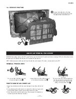
KD-34XBR2
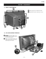
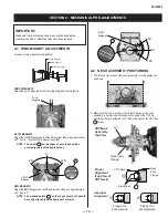
SECTION 2: MECHANICAL PRE-ADJUSTMENTS
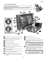
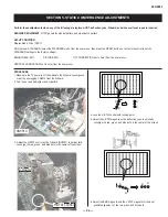
2-1. RING MAGNET ADJUSTMENTS
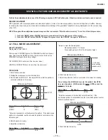
Location of ring magnets for adjustment:
Purity Magnet
BMC Magnet
V. STAT Magnet
PURITY MAGNETS
Adjust the purity magnets so that the adjusting tabs are straight up.
Purity
Magnets
V-STAT MAGNETS
Adjust the V-Stat Magnets so that the adjustment tabs are approximately
± 45° from 0° (a total of 90° between each tab)
NOTE:
The
points
(
1
) on the edges of each tab should be
evenly aligned (see the fi gure below).
V-STAT
Magnet
0˚
+45˚
-
45˚
1
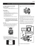
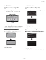
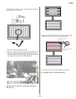
BMC MAGNETS
Adjust the BMC Magnets so that the adjustment tabs are approximately
± 40° from 90°.
NOTE: The rounded points (
1
) on the edges of each tab should
be evenly aligned (see the fi gure next column).
IMPORTANT:
Make sure that the following items are checked and adjusted
whenever the CRT or Defl ection Yoke have been replaced.
BMC
Magnet
1
90˚
130˚
50˚
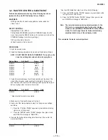
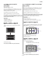
2-2. NECK ASSEMBLY POSITIONING
1. The left and right sides of the neck assembly must be straight up
and down.
2. Make sure that the rear edge of the plastic fl ange on the neck
assembly is positioned directly above the edge of the CRT pin
electrodes that are soldered to G1 within the neck of the CRT (see
1 below)
G1
Neck Ass'y
Flange
CRT/Neck
Assembly
Top View
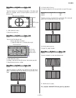
Proper
Alignment
(Top View of
CRT Neck)
Improper
Alignment
Flange Too
Far Foreward
Flange Too
Far Rearward
Electrodes
CRT Neck
Neck
Ass'y
Flange
1
Содержание KD-34XBR2 - 34" Hdtv Fd Trinitron Wega
Страница 187: ...L504 FB502 LB2016 OUH 1608 MAIN_COMB_C MAIN_COMB_Y TO P2 TO P2 3D COMB AV SW 9 965 916 02 HA3 B P3 C ...
Страница 207: ...9 965 916 02 HA3 QI P1 ...
Страница 223: ...7016 0UH 4A 9 965 916 02 HA3 QM P1 ...
Страница 264: ......
Страница 296: ......


