3-50
CCU-700A
CCU-700AP
3-10-2. ENG CANCEL Adjustment
n
• Perform the following adjustment to much the input
level of the camera system.
Rank
:
C
Equipment
:
Oscilloscope, Audio generator
To be extended
:
AT-88 board
Preparation
• MIC switch/CCU front panel
→
“CARBON”
• INCOM (PROD/PRIV/ENG) switch/
AT-88 board panel
→
“ENG”
• S2491 (INCOM 1 SELECT)/AT-88 board
→
“2W”
• Connect between pin D71 and pin B72/extension board
with 600
Z
resistor.
Test point
:
TP46 (GND: E11)/AT-88 board
Adjustment Procedure
1.
Feed the 1 kHz, 200 mV p-p sine-wave to INCOM
connector (CCU-700A/700AP).
2.
Adjust
1
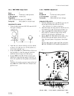
RV2452 (ENG 2W CANCEL)/AT-88 board
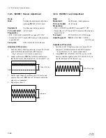
so that the audio level at TP46 (GND: E11)/AT-88
board is minimum.
3-10. 2W Intercom System Adjustment
3-10-1. ENG Level Adjustment
n
• Perform the following adjustment to much the input
level of the camera system.
Rank
:
C
Equipment
:
Oscilloscope, Audio generator
To be extended
:
AT-88 board
Preparation
• S2491 (INCOM 1 SELECT)/AT-88 board
→
“2W”
Test point
:
TP46 (GND: E11)/AT-88 board
Adjustment Procedure
1.
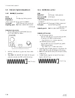
Feed the 1 kHz, 1 V p-p sine-wave to pin D71 (X) and
pin B72 (GND)/extension board.
…Fig-1 (Refer to 3-1-4. Audio connection.)
2.
Adjust
1
RV2451 (ENG 2W LEVEL)/AT-88 board so
that the audio level at TP46 (GND: E11)/AT-88 board
is 200
±
10 mV.
3-10. 2W Intercom System Adjustment
200 ± 10 mV p-p
Less than
40 mV p-p


