3-33
CCU-700 A
CCU-700AP
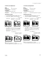
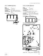
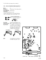
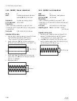
3-6-2. Return Video Deviation Adjustment
Rank
:
C
Equipment
:
Spectrum analyzer
To be extended
:
DM-94 board
Preparation
• BARS button/MSU-700
→
“OFF”
• TEST 2 button/MSU-700
→
“ON”
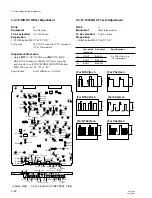
• Connect VBS 1 OUT connector and RET 1 IN connector
on CCU-700A/700AP rear panel with BNC cable.
Test point
:
TP21 (GND: E11)/DM-94 board
Adjusting point
:
1
RV20 (RET DEV)/DM-94 board
Specification
:
T = 2.000
±
0.005 MHz
3-6. RETURN VIDEO Cable
Compensation System Adjustment
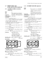
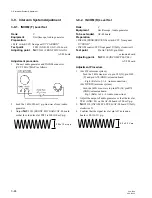
3-6-1. Return Video Carrier Frequency
Adjustment
Rank
:
C
Equipment
:
Spectrum analyzer
To be extended
:
DM-94 board
Preparation
• BARS button/MSU-700
→
“OFF”
• TEST 2 button/MSU-700
→
“ON”
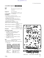
• Connect VBS 1 OUT connector and RET 1 IN connector
on CCU-700A/700AP rear panel with BNC cable.
Test point
:
TP21 (GND: E11)/DM-94 board
Adjusting point
:
1
CV1 (RET FREQ)/DM-94 board
Specification
:
69.000
±
0.005 MHz
3-6. RETURN VIDEO Cable Compensation System Adjustment
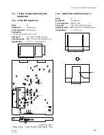
SYNC section
69.0MHz
CENT FREQ: 69.0MHz
FFEQ SPAN: 5.0MHz
69.0MHz
CENT FREQ: 69.0MHz
FFEQ SPAN: 5.0MHz
T

